Punching machine for panel processing

A sheet metal processing and punching machine technology, which is applied in the field of mechanical processing, can solve the problems of no automatic positioning system, low precise positioning of punching holes, and increased operation difficulty, etc., and achieves the effect of simple structure, convenient punching process, and reasonable structural design

Inactive Publication Date: 2016-07-27
XINCHANG COUNTY CHENGGUAN TOWN XINSHENG BEARING FACTORY
View PDF11 Cites 7 Cited by
  • Summary
  • Abstract
  • Description
  • Claims
  • Application Information

AI Technical Summary

Problems solved by technology

[0002] As a kind of light and small punching equipment widely used by people, punching machine has been widely used in various fields. It is involved in industry, construction and other industries. Punching is the process of punching the drill bit down to form a hole by gravity. , the punching machine is a further development of the punching machine. It solves the problem that the punching machine needs an independent feeding system, so the volume is small, but the punching machines currently used include ordinary punching machines and CNC punching machines, ordinary punching machines and CNC punching machines. Punching machine, ordinary punching machine has no automatic positioning system, and the precise positioning of punching is low. CNC punching machine greatly improves the accuracy and speed of punching, but increases the difficulty of operation. Therefore, it provides a safe use , and can work with high efficiency, high precision and precision. Further requirements for modern punching machines

Method used


Image

  • Punching machine for panel processing

Examples


Embodiment Construction

[0011] The following will clearly and completely describe the technical solutions in the embodiments of the present invention with reference to the accompanying drawings in the embodiments of the present invention. Obviously, the described embodiments are only some, not all, embodiments of the present invention. Based on the embodiments of the present invention, all other embodiments obtained by persons of ordinary skill in the art without making creative efforts belong to the protection scope of the present invention.

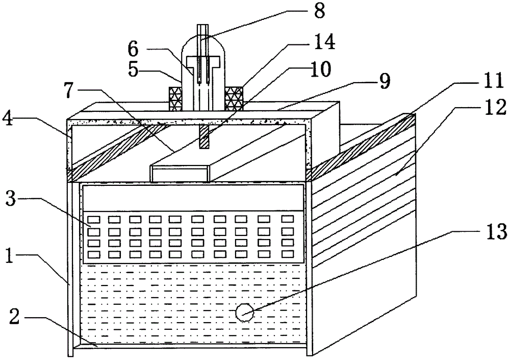
[0012] The present invention provides such figure 1 A punching machine for plate processing is shown, which includes a punching machine body 1, a support base 2 is arranged below the punching machine body 1, and longitudinal guide rails are arranged on both sides above the punching machine body 1 11. The longitudinal guide rails 11 are provided with two groups, and are symmetrically installed on the upper left and right sides of the punching machine body 1. Th...


PUM


Abstract

The invention discloses a punching machine for panel processing. The punching machine comprises a punching machine body, wherein a panel fixing rack is mounted at the middle part above the punching machine body; a regulatable and controllable punching rack is mounted above a longitudinal guide rail in a sliding manner; a horizontal guide rail is arranged above the regulatable and controllable punching rack; a driving device is arranged in the middle of the horizontal guide rail; a punching drill is mounted below the driving device; a locating instrument is mounted in the position, on the right side of the driving device, of the middle part of the horizontal guide rail; a laser transmitter is arranged above the locating instrument; a mold is arranged below the laser transmitter; a control device is arranged on the surface of the punching machine body; a power interface is arranged below the control device; and a heat dissipation window is arranged on the side surface of the punching machine body. The punching machine for panel processing has the advantages that the structure design is reasonable, the locating is accurate, the operation is convenient, the structure is simple, and the like, and can be universally popularized and utilized.

Description

technical field [0001] The invention belongs to the technical field of mechanical processing, and in particular relates to a punching machine for plate processing. Background technique [0002] As a kind of light and small punching equipment widely used by people, punching machine has been widely used in various fields. It is involved in industry, construction and other industries. Punching is the process of punching the drill bit down to form a hole by gravity. , the punching machine is a further development of the punching machine. It solves the problem that the punching machine needs an independent feeding system, so the volume is small, but the punching machines currently used include ordinary punching machines and CNC punching machines, ordinary punching machines and CNC punching machines. Punching machine, ordinary punching machine has no automatic positioning system, and the precise positioning of punching is low. CNC punching machine greatly improves the accuracy and...

Claims


Application Information

Patent Timeline
Patent Type & Authority Applications(China)
IPC IPC(8): B21D28/34B21D28/26B21D43/00
CPCB21D28/34B21D28/265B21D43/003
Inventor 龚云超吕喜德
Owner XINCHANG COUNTY CHENGGUAN TOWN XINSHENG BEARING FACTORY
Why Eureka
Try Eureka