Method for using foam light material for casting annular proving road in situ

A foam lightweight material, test track technology, applied in the direction of on-site coagulation pavement, roads, roads, etc., can solve the problem of the heavy impact of the three-dimensional curved roadbed, the inconvenient operation of the forming mold, and the impact of the mold construction demand. and other problems, to achieve the effect of reducing impracticality, convenient construction and fast construction

Active Publication Date: 2016-07-27
GUANGDONG SHENGRUI TECH CO LTD
View PDF5 Cites 2 Cited by
  • Summary
  • Abstract
  • Description
  • Claims
  • Application Information

AI Technical Summary

Problems solved by technology

The disadvantages are that post-construction settlement control is difficult, predictive detection is difficult, and there is a high possibility of uneven settlement, which has a greater impact on the heavy-duty three-dimensional arc-surface roadbed formed by filling, long construction period and high cost; especially when the This shortcoming is more prominent when part is on a soft ground
[0004] Aiming at the existing problems, the existing patent ZL201310364477.3 also provides a three-dimensional curved surface construction method of the circular test track using foam light soil, but although this method provides a feasible construction method, it is not suitable for For large or steep arcs or arcs with a relatively large height span, it is inconvenient to consider the molding mold operation required for one-time molding, and it is not practical to prepare the entire large mold, which needs to be considered during the entire construction process. In terms of the overall stability, considering the different angles of the entire circular runway, it will affect the demand for mold construction

Method used


Image

  • Method for using foam light material for casting annular proving road in situ
  • Method for using foam light material for casting annular proving road in situ

Examples


Embodiment Construction

[0021] The following will clearly and completely describe the technical solutions in the embodiments of the present invention with reference to the accompanying drawings in the embodiments of the present invention. Obviously, the described embodiments are only some, not all, embodiments of the present invention. Based on the embodiments of the present invention, all other embodiments obtained by persons of ordinary skill in the art without creative efforts fall within the protection scope of the present invention.

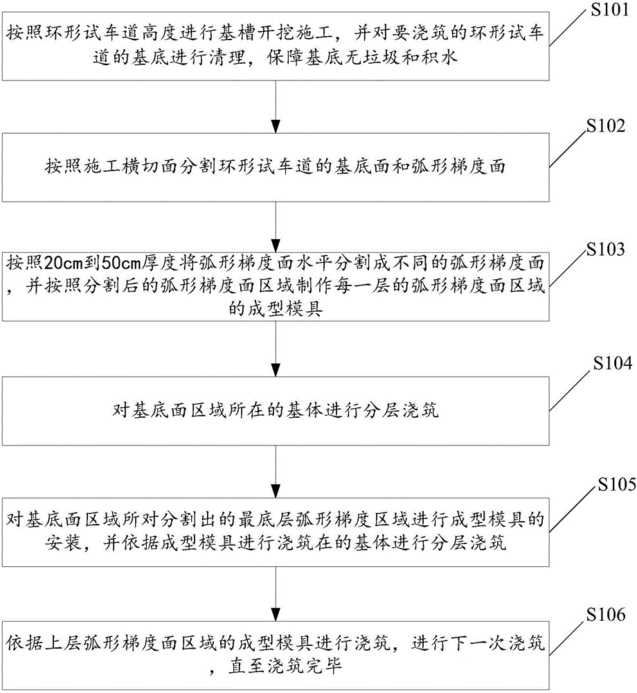
[0022] figure 1 Shown is the flow chart of the method of using the foam lightweight material cast-in-place circular test track in the embodiment of the present invention, including the following steps:

[0023] S101. Excavate the foundation trench according to the height of the circular test track, and clean the base of the circular test track to be poured to ensure that the base is free of garbage and water;

[0024] S102, dividing the base surface and the curved...


PUM

PropertyMeasurementUnit
lengthaaaaaaaaaa
densityaaaaaaaaaa
strengthaaaaaaaaaa

Abstract

The invention discloses a method for using a foam light material for casting an annular proving road in situ.The method comprises the following steps that a basal surface and an arc-shaped gradient face of the annular proving road are segmented according to the construction cross section; a forming die of an arc-shaped gradient face area on each layer is manufactured according to the segmented arc-shaped gradient face areas; a base body where the basal face area is located is cast in a layered mode; the forming die of the segmented arc-shaped gradient area on the bottommost layer is installed, and casting is carried out according to the forming die; when initial setting intensity of foam light soil on the former layer is larger than 0.3 Mpa, the segmented arc-shaped gradient face area on each layer is cast for the next time until casting is completed.The constructed foam light soil is adopted for casting the annular proving road, construction is convenient, construction speed is high, and the construction period is shortened.By segmenting the whole arc-shaped gradient face into different areas, the forming dies are prefabricated better, construction is convenient, and the different construction requirements are met.

Description

technical field [0001] The invention relates to the technical field of construction industry, in particular to a method for cast-in-situ circular test track using foam lightweight materials. Background technique [0002] The lightweight foam material is a foam product that contains a large number of small closed pores and has considerable strength by introducing air into the foam slurry according to the application needs by chemical or physical means, and after reasonable maintenance and molding, the production method is usually It is made by mechanically preparing foam agent aqueous solution into foam, and then adding the foam into the slurry composed of siliceous material, calcium material, water and various admixtures, mixing, stirring, pouring and curing. A porous material. [0003] The circular test track is an important experimental facility in the process of automobile research and development and testing, which can provide various road surfaces for automobile testin...

Claims


Application Information

Patent Timeline
Patent Type & Authority Applications(China)
IPC IPC(8): E01C9/00E01C7/08
CPCE01C7/08E01C9/001
Inventor 陈忠平汪建斌韩健陈俊霖罗勇
Owner GUANGDONG SHENGRUI TECH CO LTD
Why Eureka
Try Eureka