
In-situ heat injection slice mining section well body device of thick ore deposit of oil shale

A technology of layered mining and oil shale, applied in the fields of fluid extraction, ground mining, earthwork drilling, etc., can solve the problems of leakage, heat loss, deformation and damage of cement sheath, etc. The effect of avoiding deformation damage

Active Publication Date: 2016-07-27
TAIYUAN UNIV OF TECH
View PDF9 Cites 2 Cited by
  • Summary
  • Abstract
  • Description
  • Claims
  • Application Information

AI Technical Summary

Problems solved by technology

[0007] The purpose of the present invention is to overcome the shortcomings of the prior art, provide a wellbore device for in-situ heat injection layered mining section of oil shale thick ore seam, solve the problem of traditional wellbore device for in-situ injection of thick and extra-thick oil shale seam When thermal layering is mined, not only it is very easy to cause deformation and damage of casing and cement sheath and leakage, but also the technical problem of serious heat loss

Method used


Image

  • In-situ heat injection slice mining section well body device of thick ore deposit of oil shale

Examples


Embodiment 1

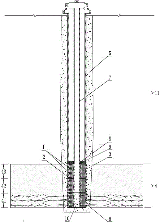
[0019] Such as figure 1 As shown, a wellbore device for the in-situ heat injection layered mining section of thick oil shale layers is formed by connecting three vacuum corrugated casings 1 with a length of 5 m. The vacuum corrugated casing 1 is composed of two outer diameters Different metal bellows (one with an outer diameter of 240mm; the other with an outer diameter of 200mm.) are set together, and then connected by an annular blind plate 2, and multi-layer heat insulation is wound in the annular gap between the two metal bellows material 3, and then vacuumize; the three vacuum corrugated casings 1 are placed in the oil shale ore section 4 in the open hole, and are respectively connected to the lower section 41 of the ore body, the middle section 42 of the ore body, and the upper section 43 of the ore body Corresponding.

Embodiment 2

[0021] Such as figure 1 As shown, a wellbore device for the in-situ heat injection layered mining section of thick oil shale layers is formed by connecting six vacuum corrugated casings 1 with a length of 20 m. The vacuum corrugated casing 1 is composed of two outer diameters Different metal bellows (one with an outer diameter of 550mm; the other with an outer diameter of 400mm.) are set together and connected by an annular blind plate 2, and multi-layer heat insulation is wound in the annular gap between the two metal bellows material 3, and then vacuumize; the 6 vacuum corrugated casings 1 are placed in the oil shale ore section 4 in the open hole, corresponding to the 6 ore body segment positions (not shown in the figure).

Embodiment 3

[0023] Such as figure 1 As shown, a wellbore device for the in-situ heat injection layered mining section of thick oil shale layers is formed by connecting 10 vacuum corrugated casings 1 with a length of 30 m. The vacuum corrugated casing 1 is composed of two outer diameters Different metal bellows (one with an outer diameter of 800mm; the other with an outer diameter of 500mm.) are set together, and then connected by an annular blind plate 2, and multi-layer heat insulation is wound in the annular gap between the two metal bellows material 3, and then vacuumize; 10 vacuum corrugated casings 1 are placed in the oil shale ore section 4 in the open hole, corresponding to the 10 ore body segment positions (not shown in the figure).

[0024] Such as figure 1 As shown, the thick oil shale target thermal injection mining area is selected, a near-horizontal single oil shale layer with a thickness of 60 m and a buried depth of 11 is 160 m. Sections are respectively the subsection 41...


PUM


Abstract

An in-situ heat injection slice mining section well body device of a thick ore deposit of oil shale belongs to the technical field of in-situ heat injection mining of the oil shale, aiming at solving the technical problems that a sleeve and a cement ring are deformed and damaged and have leakage when a traditional well body device is used for the in-situ heat injection mining of the thick and extremely thick ore deposits of the oil shale, and that the heat loss is serious. The in-situ heat injection slice mining section well body device is composed of a plurality of vacuum corrugated sleeves; each vacuum corrugated sleeve is formed through sleeving two metal corrugated sleeves with different outer diameters and connecting through an annular blind plate; a plurality of layers of heat insulation materials are wound in an annular gap of the two metal corrugated sleeves, and vacuumization is carried out; the vacuum corrugated sleeves are arranged in oil shale ore deposits in an open-hole well, and the length of each vacuum corrugated sleeve is the same as that of each oil shale ore deposit. The in-situ heat injection slice mining section well body device of the thick ore deposit of the oil shale, provided by the invention, is used for injecting steam in the thick and extremely thick ore deposits in situ for mining oil gas; the slice mining section well body device can be used for effectively protecting the heat injection sleeve and the cement ring, and the loss of heat is greatly reduced.

Description

technical field [0001] The invention belongs to the technical field of in-situ heat injection mining of oil shale, and in particular relates to an in-situ heat injection layered mining section well device for thick and extra-thick oil shale deposits. Background technique [0002] As we all know, the main pyrolysis temperature range of organic matter in oil shale is 300-500°C, so to completely convert the organic matter in oil shale into shale oil and pyrolysis gas, the oil shale must be heated to above 500°C , which is the primary condition that must be met in all methods of heating oil shale to develop oil and gas resources. [0003] In-situ heat injection of oil shale described in the authorized invention patent "Convective heating oil shale oil and gas extraction method (patent number: ZL200510012473.4) and an oil shale oil and gas resources in-situ extraction method (ZL201310057719.4)" The basic principles of oil and gas exploitation are as follows: arrange and construc...

Claims


Application Information

Patent Timeline
Patent Type & Authority Applications(China)
IPC IPC(8): E21B43/17E21C41/16
CPCE21B43/17E21C41/16
Inventor 康志勤赵阳升杨栋梁卫国赵静冯子军耿毅德
Owner TAIYUAN UNIV OF TECH
Learn More