
Patsnap Eureka
For R&D, Patsnap Eureka makes reading and utilizing patents & technical documents easy.
Patsnap Eureka AIR
Designed for self-driven R&D workflows. Generate viable solutions, solve complex R&D challenges, empower your innovation with AI.

Patsnap Eureka Materials
Designed for material experts only. Revolutionize your material R&D, from search, analyze, to developing new materials.

TechResearch
Generate reliable direction feasibility study reports for your R&D in just a few steps.

TechSeek
Discover and master advanced knowledge NOW. Basics, ideas, possibilities, all at once.

TechMind
As an expert in R&D Theories, TechMind can generates customized viable solutions instantly.

TechRisk
Analyze your overall solution with one click, know your potential R&D risks in advance.

TechMonitor
Get weekly tech updates, stay abreast of the latest tech innovations and key insights.
Turn signal lamp
A technology for turn signal lights and lamp chambers, which is applied in optical signals, signal devices, motor vehicles, etc., can solve the problems of increased aerodynamic resistance of vehicles and large-scale turn signals, and achieves suppression of air resistance, large-scale improvement, and suppression of growth. big effect
- Summary
- Abstract
- Description
- Claims
- Application Information
AI Technical Summary
Problems solved by technology
Method used
Image

Examples
no. 1 approach
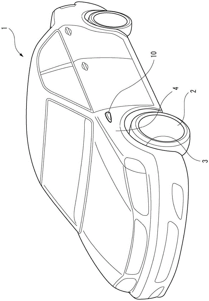
[0037] figure 1 It is a perspective view of a vehicle 1 equipped with a turn signal lamp 10 according to the first embodiment of the present invention. Such as figure 1 As shown, at least a part of the turn signal lamp 10 is disposed on the side of the vehicle body. The turn signal lamp 10 is provided on the front fender 4 forming the wheel house 3 of the front wheel 2 . A pair of left and right turn signal lamps 10 are respectively provided on the right side and the left side of the vehicle 1 .
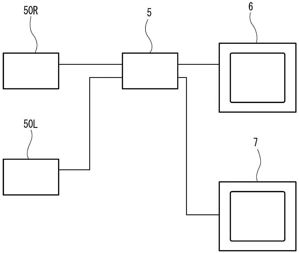
[0038] exist figure 1 The vehicle 1 shown is not provided with sandboard mirrors and reverse mirrors. The rear viewing function of the sandboard mirror and the side-view mirror is performed by the camera 50 mounted on the turn signal lamp 10 which will be described later. The right turn signal lamp provided on the right side of the vehicle 1 includes a right camera inside. The left turn signal lamp provided on the left side of the vehicle 1 includes a left camera inside. The r...
no. 2 approach
[0074] Figure 8 It is an exploded perspective view of a turn signal lamp 10A according to the second embodiment of the present invention. Such as Figure 8 As shown, the turn signal lamp 10A according to the present embodiment differs from the first embodiment in the shape of the light guide 30A. The light guide body 30A does not have a sub-light guide portion. The turn signal lamp 10A according to the present embodiment can light the main light portion 32A using the light that lighted the sub light guide portion 33 in the turn signal lamp 10 according to the first embodiment, so that the main light portion 32A can be made to emit light more brightly.
[0075] In the present embodiment, the light guide body 30A is arranged in a region extending from the camera 50 in a direction along the surface of the front fender 4 . Therefore, visibility can be improved and an increase in air resistance due to the turn signal lamp 10A can be suppressed.
no. 3 approach
[0077] Figure 9 It is an exploded perspective view of a turn signal lamp 10B according to the third embodiment of the present invention. Such as Figure 9 As shown, the turn signal lamp 10B according to the present embodiment differs from the first embodiment in the shapes of the lamp body 11B, the light guide body 30B, the additional body 40B, and the housing 12 .
[0078] The light guide 30B has an incident part 31B, a rear end part 34B located above the camera 50, a main light guide part 32B, and a sub light guide part 33B. The main light part 32B is an arched part, and connects the incident part 31B and the rear end part 34B in an arched shape. The sub light guide portion 33B is a plate-shaped portion extending downward from the main light guide portion 32B. The sub light guide part 33B is provided with a slit extending in the vertical direction. The thickness in the left-right direction of the sub light guide part 33B is smaller than the thickness in the left-right d...
PUM
 Abstract
Description
Claims
Application Information
 - R&D Engineer
- R&D Manager
- IP Professional
- Industry Leading Data Capabilities
- Powerful AI technology
- Patent DNA Extraction
Browse by: Latest US Patents, China's latest patents, Technical Efficacy Thesaurus, Application Domain, Technology Topic, Popular Technical Reports.
© 2024 PatSnap. All rights reserved.Legal|Privacy policy|Modern Slavery Act Transparency Statement|Sitemap|About US| Contact US: help@patsnap.com