
Submarine pipeline complex load joint loading test device

A technology of combined loading and complex loading, applied in measuring devices, instruments, scientific instruments, etc., can solve the problems of single external load, inability to realize local stability test, and inability to realize the joint action of multiple loads, and achieve safety calibration. nuclear effect

Inactive Publication Date: 2018-06-12
TIANJIN UNIV
View PDF13 Cites 0 Cited by
  • Summary
  • Abstract
  • Description
  • Claims
  • Application Information

AI Technical Summary

Problems solved by technology

[0005] 1. The external load that can be simulated by domestic and foreign deep-water pressure chambers is single, mainly due to the influence of axial tension or bending moment under the action of water pressure on the mechanical properties of submarine pipelines, and local stability tests under the combined action of multiple loads cannot be realized
[0006] 2. Relevant devices at home and abroad cannot realize the dynamic test of submarine pipeline specimens under high pressure by applying radial bidirectional vibration, axial tension and compression and torque composite loads at the same time under the action of high water pressure
[0007] 3. Relevant devices at home and abroad cannot realize the dynamic test of deepwater riser specimens under high pressure by applying axial and radial vibration loads at the same time under the action of high water pressure
[0008] The existing test device (such as patent application number: CN201110008538) has realized the test of a full-scale pipeline, but it is only a single application of external loads, and cannot realize the joint action of multiple loads

Method used


Image

  • Submarine pipeline complex load joint loading test device
  • Submarine pipeline complex load joint loading test device
  • Submarine pipeline complex load joint loading test device

Examples


Embodiment Construction

[0035] Below in conjunction with accompanying drawing, the specific embodiment of the present invention will be further described:

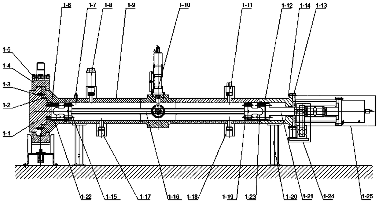
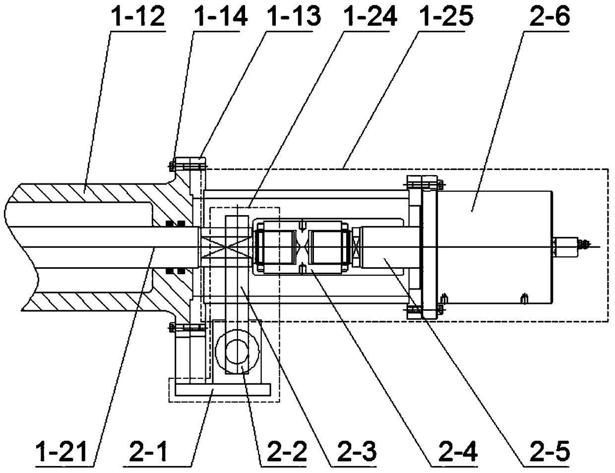
[0036] Such as figure 1 As shown, the combined loading buckling test device of the scale deep-water submarine pipeline mainly includes: end cover 1-1, cylinder end 1-6, cylinder main body 1-5, cylinder tail 1-12 and cylinder body The axial force-torque combined loading device connected at the tail is composed of a torque loading device 1-24 and an axial force loading device 1-25. The whole cylinder part is fixed on the ground by the saddle 1-20. The front end of the cylinder is closed by setting the positioning pin 1-3 and the clamp 1-4, and the sealing ring 1-2 keeps the seal. The cylinder body is provided with several openings, including a safety valve 1-8, a water injection port 1-17, a drainage hole 1-18, an exhaust hole 1-11 and a pressurizing hole 1-7. The middle part of the device is provided with two openings on the top and the side, and...


PUM


Abstract

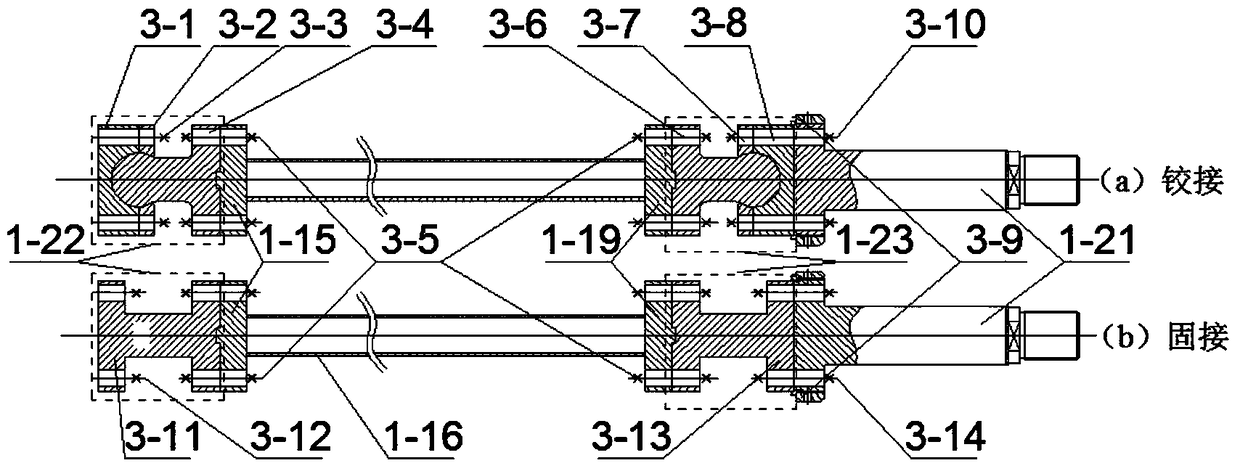
The invention relates to a combined loading testing device for complex loads of submarine pipelines. The combined loading testing device comprises an end cover (1-1), a cylinder end part (1-6), a cylinder main body (1-5) and a cylinder tail (1-12), wherein a front-end sealing flange (1-15) and a tail-end sealing flange (1-19) are welded to two ends of a testing pipe fitting (1-16), respectively, holes are formed in the top and the side part of the cylinder main body (1-5), respectively, and vibrating devices (1-10) are mounted at the two holes and are used for applying vibrating loads to the testing pipe fitting along the radial direction; an axial force-torque combined loading device is connected to the cylinder tail (1-12) through a connecting assembly (1-13); the tail-end sealing flange (1-19) is connected with a connecting shaft (1-21) through a tail-end connecting assembly (1-23), and the connecting shaft (1-21) stretches out of a cylinder and is connected with the axial force-torque combined loading device. According to the combined loading testing device, the approximate simulation of deepwater pipelines and vertical pipes under different limiting conditional loads is provided.

Description

technical field [0001] The invention relates to a combined loading test device for complex loads of submarine pipelines, which can realize the joint action of axial tension and compression, vibration, torque and external pressure loads on a scaled pipeline test piece, and approximate simulation of submarine pipelines and standpipes in the test. The real operating environment during installation and service enables in-depth exploration of the failure modes of deepwater pipelines and risers under different load combinations. Background technique [0002] Energy security and the core competitiveness of the world economy are increasingly dependent on the utilization and development of marine resources. However, my country's offshore oil and gas exploration and development technology still has a large gap compared with the world's advanced level. It is necessary to accelerate the innovation of deep-sea oil and gas development technology and enter the "deep-sea era". [0003] Amo...

Claims


Application Information

Patent Timeline
Patent Type & Authority Patents(China)
IPC IPC(8): G01N3/00
CPCG01N3/00
Inventor 樊志远余建星余杨孙震洲段晶辉刘杰王华昆
Owner TIANJIN UNIV
Learn More