Air intake structure of indoor air environment monitoring equipment

A technology for environmental monitoring and indoor air, which is applied to the structural details of gas analyzers, measuring devices, and analyzing gas mixtures. It can solve problems such as blocking, affecting appearance, and damaging electrical components. The effect of the element

Active Publication Date: 2017-07-07
中科同德(北京)生态科技有限公司
View PDF1 Cites 0 Cited by
  • Summary
  • Abstract
  • Description
  • Claims
  • Application Information

AI Technical Summary

Problems solved by technology

The detector disclosed in this patent is in the shape of a cuboid, and the air inlet and the air outlet are arranged on the front of the casing. When placed, they are mostly facing upward or backward, which is more likely to cause foreign matter to enter, block or damage electrical components. Directly below, exposed to the outside, affecting the appearance

Method used


Image

  • Air intake structure of indoor air environment monitoring equipment
  • Air intake structure of indoor air environment monitoring equipment
  • Air intake structure of indoor air environment monitoring equipment

Examples


Embodiment 1

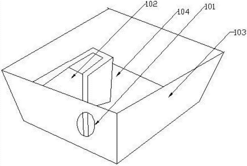
[0034] Such as figure 1 As shown, a kind of air inlet structure of indoor air environment monitoring equipment, the air inlet structure is set on the base of the indoor air environment monitoring equipment, the base is square, including a hole 101 and a set for connecting the hole 101 with the detection air duct Air structure 102, the edge of the base is bent upwards to form a bent surface 103, and the middle part is a plane for stably placing the indoor air environment monitoring equipment. The hole is set on the bent surface 103, half of the hole 101 is connected The gas-collecting structure 102 is connected, and a detection air duct is provided in the body. The gas-collecting structure 102 is connected with the detection air duct, and the detection gas is introduced into the detection air duct. The electrical room 104 communicates.

[0035]Wherein, the shape of the base can also be any shape such as a circle, a rectangle, a rhombus, and an ellipse.

[0036] By bending the...

Embodiment 2

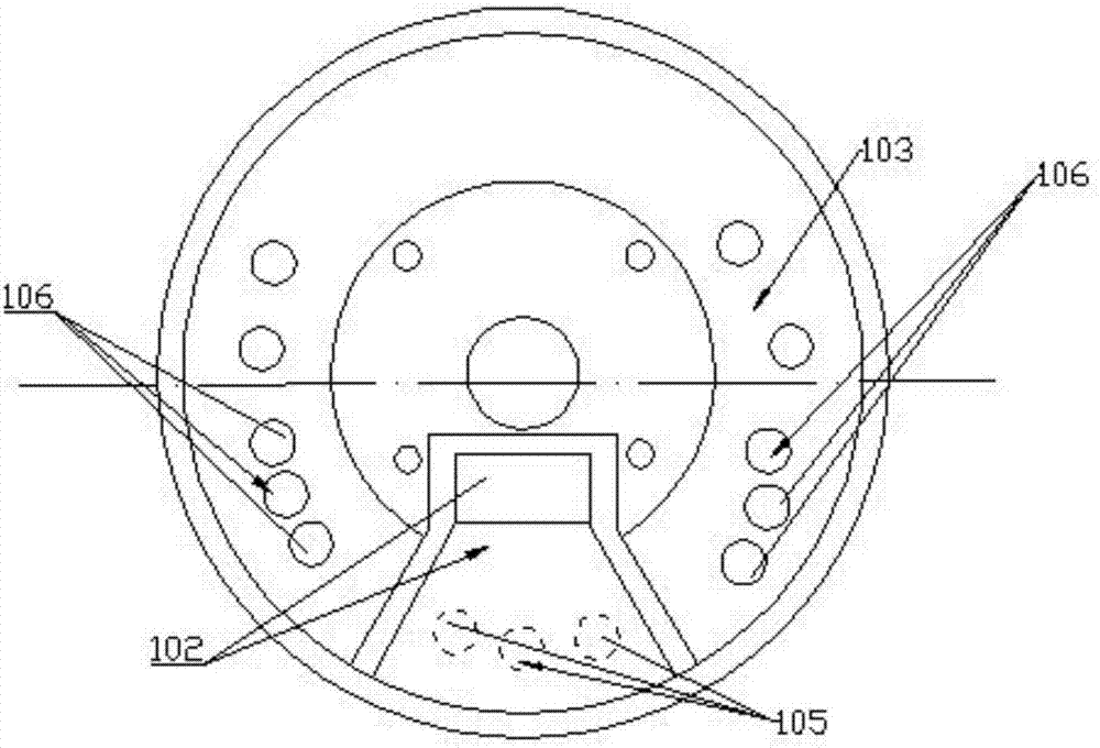
[0038] Such as figure 2 As shown, the difference from Embodiment 1 is that the base is circular, and the base of the indoor air environment monitoring device is provided with a plurality of holes. 105 groups, the group of holes connected with the electrical room is 106 groups of cooling holes, the group of 105 air intake holes is one group, the group of 106 cooling holes is two groups, and the two groups of cooling holes 106 are respectively arranged on the left and right sides of the group of 105 air intake holes On both sides, groups of air intake holes 105 and groups of cooling holes 106 are arranged circumferentially along the bending surface 103 and cover half of the bending surface, wherein the groups of air inlet holes 105 are connected with the gas-collecting structure 102, and the gas-collecting structure 102 is connected with the detection wind. The air inlet of the duct is connected, and the gas enters the gas-collecting structure 102 through the air inlet 105 and ...

Embodiment 3

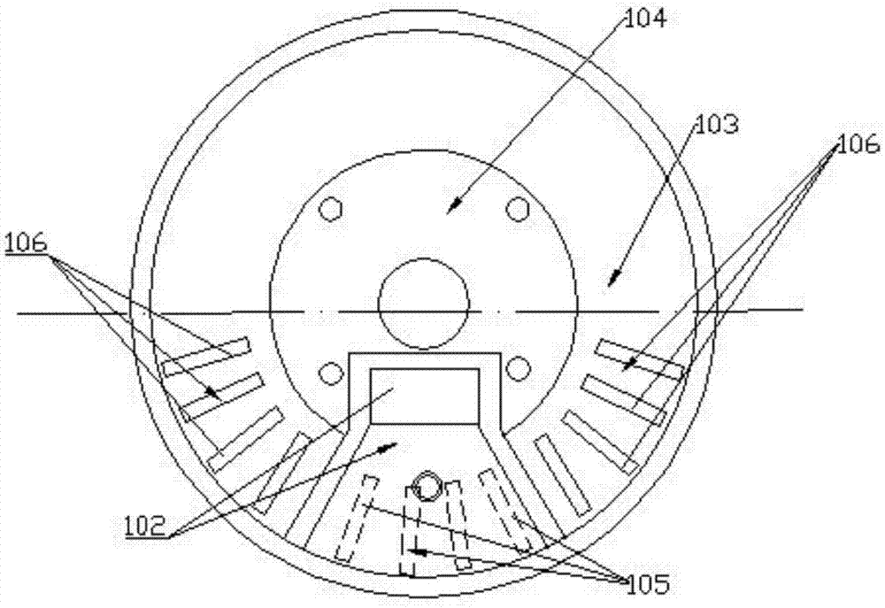
[0041] Such as image 3 As shown, the difference from Embodiment 2 is that the group of air intake holes 105 is set in the middle of the front of the base, and the two sides of the group of air intake holes 105 are respectively provided with a group of left heat dissipation holes and a group of right heat dissipation holes. The electrical room 104 of the component is located at the rear of the base, and the air intake hole 105 and the cooling hole 106 can also be arranged on the back side of the base. The hole group and the heat dissipation hole group can be set on the opposite side of the installation position of the electrical components; the air intake hole and the heat dissipation hole are opened on the bending surface 103 according to the curvature of the bending surface, and each air intake hole 105 and heat dissipation hole 106 The shape is elongated, each hole extends from the lower edge of the bending surface to the upper edge, the lower edge of the hole is slightly h...


PUM


Abstract

The invention discloses an air intake structure for an indoor air environment monitoring device. The air intake structure is arranged on a base of the indoor air environment monitoring device and comprises at least one hole and an air collecting structure used for connecting the hole with a detection air flue, wherein an edge of the base is upward bent and formed into a bent surface; the holes are formed in the bent surface; certain holes are communicated with the air collecting structure and are used for guiding the detected air into the detection air flue; the other holes are communicated with an electric apparatus chamber which is arranged in the indoor air environment monitoring device and is used for mounting electric elements. According to the air intake structure provided by the invention, the edge of the base is upward bent and formed into the bent surface, the holes are formed on the bent surface and the holes are higher than the placing plane for a certain distance, and even if water or other foreign matter is on the plane, the water or other foreign matter cannot enter into the indoor air environment monitoring device. Through the air intake structure provided by the invention, the holes are located on inclined lower side of the base, so that the above foreign matter also cannot enter into the indoor air environment monitoring device through the holes. Due to the design, the interior of the shell is excellently isolated from the external environment.

Description

technical field [0001] The invention belongs to the field of environmental detection equipment components, and in particular relates to an air intake structure of indoor air environment monitoring equipment. Background technique [0002] In recent years, the problem of air pollution has become more and more serious, especially regional air pollution. Smog affects people's travel, and fine particle pollution such as PM2.5 has attracted widespread attention from the public. The composition of outdoor pollutants is complex, resulting in indoor gas pollution from traditional formaldehyde, carbon monoxide and other harmful gases to gas-solid comprehensive pollution caused by formaldehyde, carbon monoxide and PM2.5 particles. The air quality situation in the environment is also getting more and more attention. [0003] At present, for the detection of indoor air on the market, hand-held detectors are mostly used. This type of detection equipment has the advantages of being easy t...

Claims


Application Information

Patent Timeline
Patent Type & Authority Patents(China)
IPC IPC(8): G01N33/00
CPCG01N33/0009G01N33/0016
Inventor 苏晓丹冯启源贾永超徐广勇马建伟
Owner 中科同德(北京)生态科技有限公司
Why Eureka
Try Eureka