Supercharge Your Innovation With Domain-Expert AI Agents!

Light guide plate and light source module

A light source module and light guide plate technology, which is applied in light guides, optics, optical components, etc., can solve problems affecting the uniformity of the surface light source, affecting the distribution of light patterns of the surface light source, and affecting the optical quality of the light source module, so as to reduce scratches on the bottom surface or Chance of rubbing, good optical quality, effect of reducing generation of bright spots

Active Publication Date: 2019-02-26
YANGXIN TECH SUZHOU
View PDF14 Cites 0 Cited by
  • Summary
  • Abstract
  • Description
  • Claims
  • Application Information

AI Technical Summary

Problems solved by technology

However, due to the different sizes of different dots, the configuration of the above two dots may affect the light pattern distribution of the surface light source emitted from the light guide plate (such as affecting the uniformity of the surface light source), thus affecting the light source applied to the light guide plate. Optical taste of the module

Method used


Image

  • Light guide plate and light source module
  • Light guide plate and light source module
  • Light guide plate and light source module

Examples


Embodiment Construction

[0028] The aforementioned and other technical contents, features and effects of the present invention will be clearly presented in the following detailed description of multiple embodiments with accompanying drawings. The directional terms mentioned in the following embodiments, such as up, down, front, back, left, right, etc., are only directions referring to the drawings. Accordingly, the directional terms are used to illustrate, not to limit, the invention.

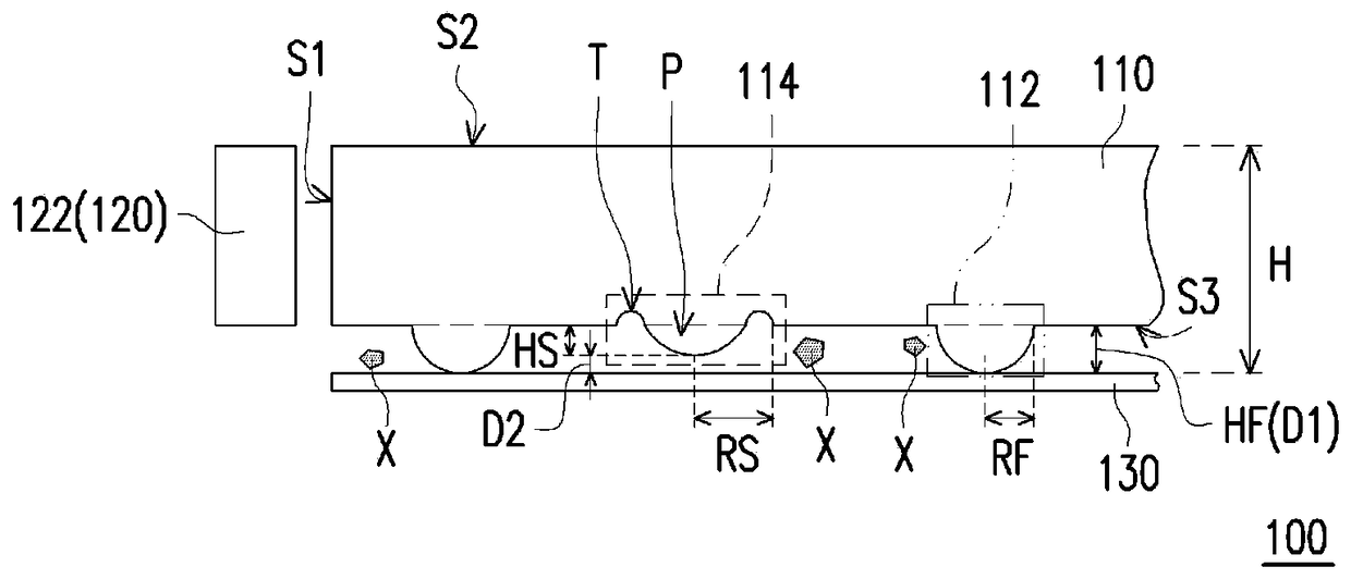
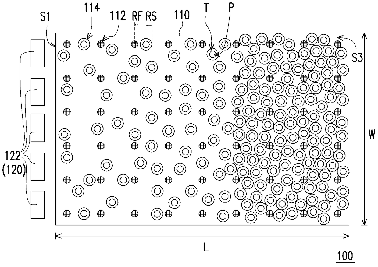
[0029] Figure 1A is a partial cross-sectional schematic diagram of a light source module according to an embodiment of the present invention. Figure 1B It is a schematic bottom view of a light source module according to an embodiment of the present invention. In order to clearly indicate the first outlet and the second outlet, Figure 1B omitted from Figure 1A reflective sheet. Please refer to Figure 1A and Figure 1B , the light source module 100 of this embodiment includes a light guide plate 110 and a light ...


PUM


Abstract

The invention provides a light guide plate which comprises a light incident surface, a light out surface and a bottom surface. The light out surface is perpendicular to the light incident surface and is connected to the light incident surface. The bottom surface is connected to the light incident surface relative to the light out surface. A plurality of first lattice points and a plurality of second lattice points are formed in the bottom surface, wherein the point diameter depth of each first lattice point is HF, the point diameter depth of each first lattice point is HS, and the difference between HF and HS is larger than 1 um and smaller than 15um. The invention also provides a light source module. Through the lattice points with different depths in the light guide plate provided by the invention, the scratch and wear of the light guide plate can be reduced, and the light source module provided by the invention has excellent optical taste.

Description

technical field [0001] The present invention relates to a light guide plate and a light source module, and in particular to a light guide plate and a light source module capable of reducing scratches. Background technique [0002] Generally speaking, the light source modules can be divided into direct-type light source modules and side-type light source modules. Taking the side-entry light source module as an example, it generally includes a light guide plate, a reflection sheet located under the light guide plate, and a light source located on the side of the light guide plate. After the light beam emitted by the light source enters the light guide plate from the light incident surface on the side of the light guide plate, it will be guided into the entire light guide plate due to total reflection. The multiple dots located on the bottom of the light guide plate will destroy the total reflection of light, allowing the light beam to be emitted from the light emitting surfac...

Claims


Application Information

Patent Timeline
Patent Type & Authority Patents(China)
IPC IPC(8): G02B6/00F21V8/00
Inventor 陈俊伟王静杨越峰郭浩然
Owner YANGXIN TECH SUZHOU
Features
  • R&D
  • Intellectual Property
  • Life Sciences
  • Materials
  • Tech Scout
  • Unparalleled Data Quality
  • Higher Quality Content
  • 60% Fewer Hallucinations
Learn More