Coating equipment and method for tube-type PERC solar cells

A technology of solar cells and coating equipment, applied in the direction of circuits, photovoltaic power generation, electrical components, etc., can solve problems affecting the uniformity of Al2O3 coating, affecting the qualified rate of finished batteries, affecting the EL yield of batteries, etc., to achieve the reduction of EL Scratch ratio, good self-lubricating performance, and the effect of saving production time

Active Publication Date: 2017-10-24
GUANGDONG AIKO SOLAR ENERGY TECH CO LTD +1
View PDF4 Cites 25 Cited by
  • Summary
  • Abstract
  • Description
  • Claims
  • Application Information

AI Technical Summary

Problems solved by technology

[0007] However, using tubular PECVD to make the back film of the PERC battery, scratches seriously affect the qualified rate of the finished battery. The problem is that, during the process of inserting the wafer into the graphite boat, the front side of the silicon wafer will contact the graphite boat wall, and the PN junction on the front side will be damaged. Scratches, resulting in scratches in the EL test, affecting the electrical performance of the battery
[0010] However, the resistivity of silicon nitride is very high, which affects the uniformity of the aluminum oxide coating on the back. EL testing will produce black edges at the corners, black edges at stuck points, etc., which will affect the EL yield of the battery. It is also found in production that there are The battery conversion efficiency of EL black edge is obviously lower
Silicon nitride plating on inserts consumes a lot of silicon wafers, because it takes a long time for the inserts to be coated, and the silicon wafers will be greatly bent because the surface coating is too thick, resulting in the interruption of the coating process and the need for re-plating, which takes up production time
Use some unqualified chips, the degree of bending is greater, so the silicon wafers inserted into the boat should not be too bad, which will seriously consume the silicon wafers, and the cost is high

Method used


Image

  • Coating equipment and method for tube-type PERC solar cells
  • Coating equipment and method for tube-type PERC solar cells
  • Coating equipment and method for tube-type PERC solar cells

Examples


Embodiment 1

[0132] (1) Put the graphite boat into the tubular PECVD coating equipment for drying, the drying temperature is 300 degrees, and the drying time is 20 minutes;

[0133] (2) After drying the boat, put the graphite boat into the tubular PECVD coating equipment again, and coat at least one layer of silicon carbide film on the surface of the graphite boat. The coating method of the silicon carbide film is as follows:

[0134] Raise the temperature to 380°C, inject ammonia gas, the plasma power is 2000w, the flow rate is 1slm, and the time is 2min;

[0135] Feed methane and silane, the methane flow rate is 2slm, the silane flow rate is 200sccm, and the time is 5s;

[0136] Methane and silane are introduced, the plasma power is 3000w, the time is 1 hour, the methane flow rate is 2slm, and the silane flow rate is 200sccm;

[0137] Cool down to 350°C and leave the boat.

[0138] (3) Place the treated silicon wafer on a graphite boat, and send it to the tubular PECVD coating equipmen...

Embodiment 2

[0144] (1) Put the graphite boat into the tubular PECVD coating equipment for drying, the drying temperature is 350 degrees, and the drying time is 25 minutes;

[0145] (2) After drying the boat, put the graphite boat into the tubular PECVD coating equipment again, and coat at least one layer of silicon carbide film on the surface of the graphite boat. The coating method of the silicon carbide film is as follows:

[0146] Raise the temperature to 400°C, inject ammonia gas, the plasma power is 3000w, the flow rate is 2slm, and the time is 3min;

[0147] Feed methane and silane, the methane flow rate is 4slm, the silane flow rate is 400sccm, and the time is 10s;

[0148] Methane and silane are introduced, the plasma power is 5000w, the time is 2 hours, the flow rate of methane is 3slm, and the flow rate of silane is 300sccm;

[0149] Cool down to 360°C and leave the boat.

[0150] (3) Place the treated silicon wafer on a graphite boat, and send it to the tubular PECVD coating ...

Embodiment 3

[0156] (1) Put the graphite boat into the tubular PECVD coating equipment for drying, the drying temperature is 370 degrees, and the drying time is 30 minutes;

[0157] (2) After drying the boat, put the graphite boat into the tubular PECVD coating equipment again, and coat at least one layer of silicon carbide film on the surface of the graphite boat. The coating method of the silicon carbide film is as follows:

[0158] Raise the temperature to 420°C, inject ammonia gas, the plasma power is 4000w, the flow rate is 5slm, and the time is 5min;

[0159] Feed methane and silane, the methane flow rate is 5slm, the silane flow rate is 500sccm, and the time is 15s;

[0160] Methane and silane are introduced, the plasma power is 6000w, the time is 1.5 hours, the methane flow rate is 4slm, and the silane flow rate is 500sccm;

[0161] Cool down to 380°C and leave the boat.

[0162] (3) Place the treated silicon wafer on a graphite boat, and send it to the tubular PECVD coating equi...


PUM

PropertyMeasurementUnit
depthaaaaaaaaaa
diameteraaaaaaaaaa
angleaaaaaaaaaa

Abstract

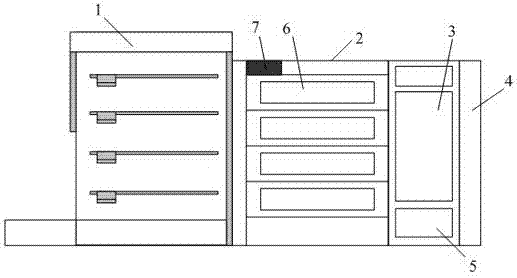
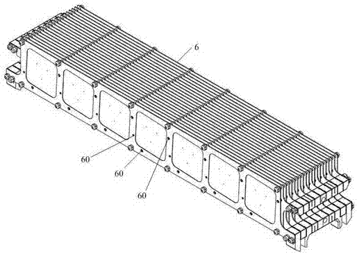
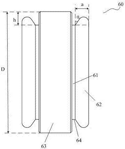
The invention discloses coating equipment for tube-type PERC solar cells. The coating equipment comprises a wafer loading region, a furnace body, a gas cabinet, a vacuum system, a heating system, a control system and a graphite boat; the gas cabinet is provided with a first gas pipeline for introducing silane, a second gas pipeline for introducing ammonia, a third gas pipeline for introducing trimethylaluminum, a fourth gas pipeline for introducing laughing gas and a fifth gas pipeline for introducing methane; the graphite boat is used for loading or unloading a silicon wafer; before being used or after being coated many times, the graphite boat needs to be subjected to pretreatment comprising the steps: drying the graphite boat; and coating at least one layer of silicon carbide film on the surface of the dried graphite boat. Correspondingly, the invention further discloses a coating method for tube-type PERC solar cells. By using the coating equipment and method, the pretreatment step of the graphite boat is simplified, the consumption of the silicon wafer is reduced, the silicon wafer is prevented from being scratched, and the EL yield of the cells is increased.

Description

technical field [0001] The invention relates to the field of PERC solar cells, in particular to a coating device for a tubular PERC solar cell and a coating method for a tubular PERC solar cell. Background technique [0002] With the higher and higher requirements for the photoelectric conversion efficiency of crystalline silicon cells, people began to study the back passivation solar cell technology. The current mainstream method is to use plate PECVD to coat the back. Plate PECVD consists of different chambers. Each chamber is coated with a layer of film. Once the equipment is fixed, the number of layers of the composite film has been fixed. Therefore, the disadvantages of plate PECVD are: The combination of composite films cannot be flexibly adjusted, and the passivation effect of the back film cannot be better optimized, thereby limiting the photoelectric conversion efficiency of the battery. At the same time, plate PECVD uses an indirect plasma method, and the passivat...

Claims


Application Information

Patent Timeline
Patent Type & Authority Applications(China)
IPC IPC(8): C23C16/455C23C16/458H01L31/18
CPCC23C16/455C23C16/4581H01L31/1868Y02E10/50Y02P70/50
Inventor 林刚正方结彬赖俊文何达能陈刚
Owner GUANGDONG AIKO SOLAR ENERGY TECH CO LTD
Why Eureka
Try Eureka