Data transmission method and device
A data transmission method and a technology of a data transmission device, which are applied in the field of communication, can solve problems such as no multiple nodes sharing a carrier, and achieve the effects of reducing waste of resources and improving transmission performance
- Summary
- Abstract
- Description
- Claims
- Application Information
AI Technical Summary
Problems solved by technology
Method used
Image
Examples
Embodiment 1
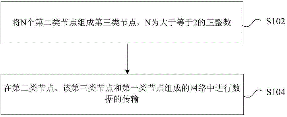
[0122] Figure 7 is a schematic diagram of a data transmission method according to an embodiment of the present invention, such as Figure 7 As shown, N (N=4) second-type nodes are combined to form a third-type virtual node with multi-carrier capability, and the above-mentioned N second-type nodes have M1, M2, ... M N carrier capability, the above-mentioned third type of node has equal to M=M1+M2+...+M N A carrier-capable node.
[0123] Optionally, the above-mentioned third type of virtual node is an aggregation node, which aggregates different nodes in units of component carriers, thereby forming a composite node, such as: enhanced carrier capability, enhanced processing capability, enhanced connection scheme, etc. .
Embodiment 2
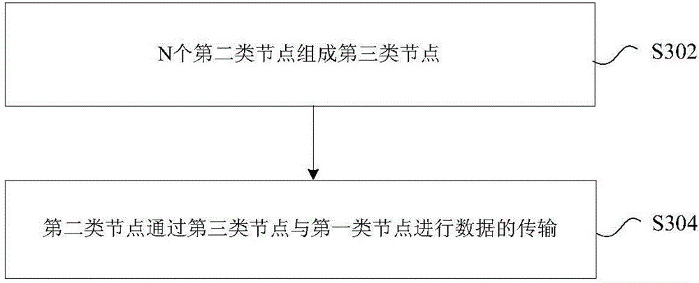
[0125] Figure 8 is a schematic diagram (1) of a data transmission method according to an embodiment of the present invention, such as Figure 8 As shown, N (N=2) second-type nodes are combined to form a third-type node with multi-carrier capability, and the second-type node 1 and the second-type node 2 each have the capability of one carrier (M1=M2 =1), the second type node 1 and the second type node 2 receive the data sent from the first type node on M (M=2) carriers; the above-mentioned second type node 1 will receive the above-mentioned first type The data of the node is then forwarded to the second type node 2 in the third type node.
[0126] The data transmission between the second type node 1 and the second type node 2 can be transmitted by wireless communication or wired communication.
Embodiment 3
[0128] Figure 9 is a schematic diagram (2) of a data transmission method according to an embodiment of the present invention, such as Figure 9 As shown, N (N=2) second-type nodes are formed into a third-type node with multi-carrier capability, wherein the second-type node 2 with new-type carrier capability receives signals from one or more first-type nodes Sending data on a carrier of a new type; the node 2 of the second type forwards the received data of the node of the first type to the node 1 of the second type in the node of the third type.
[0129] The data transmission between the second type node 1 and the second type node 2 can be transmitted by wireless communication or wired communication.
PUM
 Abstract
Description
Claims
Application Information
 - R&D
- Intellectual Property
- Life Sciences
- Materials
- Tech Scout
- Unparalleled Data Quality
- Higher Quality Content
- 60% Fewer Hallucinations
Browse by: Latest US Patents, China's latest patents, Technical Efficacy Thesaurus, Application Domain, Technology Topic, Popular Technical Reports.
© 2025 PatSnap. All rights reserved.Legal|Privacy policy|Modern Slavery Act Transparency Statement|Sitemap|About US| Contact US: help@patsnap.com


