Anti-blockage hydraulic classifier

A hydraulic classifier and anti-clogging technology, which is applied in the direction of solid separation, wet separation, chemical instruments and methods, etc., can solve the problems of blockage of the discharge port, affecting the classification accuracy, and affecting the progress of the classification, so as to prevent material blockage and improve Stable output and improved work efficiency

Inactive Publication Date: 2016-08-03
杨春艳
View PDF6 Cites 3 Cited by
  • Summary
  • Abstract
  • Description
  • Claims
  • Application Information

AI Technical Summary

Problems solved by technology

[0002] At present, the principles of the industrial hydraulic classifiers used in the market are all based on the principles of fluid mechanics. According to the different particle sizes and specific gravity of solid particles, under the action of external forces, their sedimentation speeds in the liquid are different, so as to realize the material Separated according to particle size and specific gravity, fine-grained or small specific-gravity solid particles are suspended in the liquid and become overflow, coarse-grained or large-grained solid particles settle at the bottom of the tank, and are discharged along the sand discharge device to realize continuous separation of materials A kind of grading equipment; in many beneficiation operations, hydraulic classification plays an important role; but the current hydraulic classifier cannot guarantee the uniform particle classification inside the machine during the working process, and what is more serious is that the discharge port is often blocked, It not only affects the classification accuracy, but also affects the classification progress, and also brings great inconvenience to the daily maintenance of the machine

Method used


Image

  • Anti-blockage hydraulic classifier
  • Anti-blockage hydraulic classifier
  • Anti-blockage hydraulic classifier

Examples


Embodiment

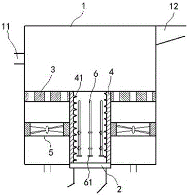
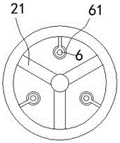
[0015] exist Figure 1 to Figure 3 In the shown embodiment, the anti-clogging hydraulic classifier includes a classification chamber 1, a feed pipe 11 and an overflow pipe 12 are respectively installed on the upper part of the classification chamber 1, and a water inlet and a discharge pipe are provided at the bottom of the classification chamber 1. feed port 2;

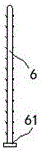
[0016] A sieve plate 3 is fixed in the classification chamber 1, and a discharge cylinder 4 is installed between the sieve plate 3 and the discharge port 2. The upper end of the discharge cylinder 4 runs through the sieve plate 3, and the discharge cylinder 4 can The axis rotates freely; the inner wall of the discharge cylinder 4 is engraved with spiral diversion lines 41, and the outer wall of the discharge cylinder 4 is engraved with transmission stripes; in the classification chamber 1, below the sieve plate 3, a hydrodynamic turbine 5 is also installed. , the rotating shaft of the hydrodynamic turbine 5 is coinc...


PUM


Abstract

The invention relates to an anti-blockage hydraulic classifier which comprises a classifying cavity. A feeding pipe and an overflow pipe are mounted on the upper portion of the classifying cavity. Water inlets and a discharge outlet are formed in the bottom of the classifying cavity. A screen plate is fixedly arranged in the classifying cavity. A discharge barrel is mounted between the screen plate and the discharge outlet, and the upper end of the discharge barrel penetrates through the screen plate. The discharge barrel can freely rotate around the own axis. Spiral flow-guiding lines are formed on the inner wall of the discharge barrel, and transmission stripes are formed on the outer wall of the discharge barrel. Hydraulic turbines are further mounted in the classifying cavity and located below the screen plate, and a rotating shaft of each hydraulic turbine coincides with the axis of the corresponding water inlet. The outer walls of the hydraulic turbines are engaged with the outer wall of the discharge barrel. According to the classifier, the discharge outlet can be effectively prevented from being blocked, material discharge is promoted, and long-term stable work of the classifier is effectively guaranteed.

Description

technical field [0001] The invention relates to an industrial grading device, in particular to a hydraulic classifier. Background technique [0002] At present, the principles of the industrial hydraulic classifiers used in the market are all based on the principles of fluid mechanics. According to the different particle sizes and specific gravity of solid particles, under the action of external forces, their sedimentation speeds in the liquid are different, so as to realize the material Separated according to particle size and specific gravity, fine-grained or small specific-gravity solid particles are suspended in the liquid and become overflow, coarse-grained or large-specific solid particles settle at the bottom of the tank, and are discharged along the sand discharge device to realize continuous separation of materials A kind of grading equipment; in many beneficiation operations, hydraulic classification plays an important role; but the current hydraulic classifier c...

Claims


Application Information

Patent Timeline
Patent Type & Authority Applications(China)
IPC IPC(8): B03B5/62
CPCB03B5/62
Inventor 沈炜
Owner 杨春艳
Why Eureka
Try Eureka