Bevel guide rail plate-shearing machine and shearing method thereof

A technology of shearing machine and guide rail, which is applied in the direction of shearing device, shearing machine equipment, cutter for shearing machine device, etc., to achieve the effect of high-efficiency automatic shearing, improved production efficiency and low frictional force

Active Publication Date: 2016-08-03
马鞍山市中亚机床制造有限公司
View PDF8 Cites 5 Cited by
  • Summary
  • Abstract
  • Description
  • Claims
  • Application Information

AI Technical Summary

Problems solved by technology

[0007] Aiming at the problem that large processing errors are easy to occur in the production and processing of the existing shearing machine, the present invention provides a shearing machine with inclined plane guide rail and its shearing method, which can automatically adjust the vertical distance between the upper knife and the lower knife. Degree and gap value, small processing error

Method used


Image

  • Bevel guide rail plate-shearing machine and shearing method thereof
  • Bevel guide rail plate-shearing machine and shearing method thereof
  • Bevel guide rail plate-shearing machine and shearing method thereof

Examples


Embodiment 1

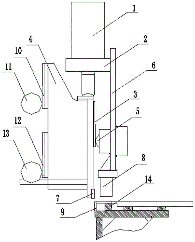
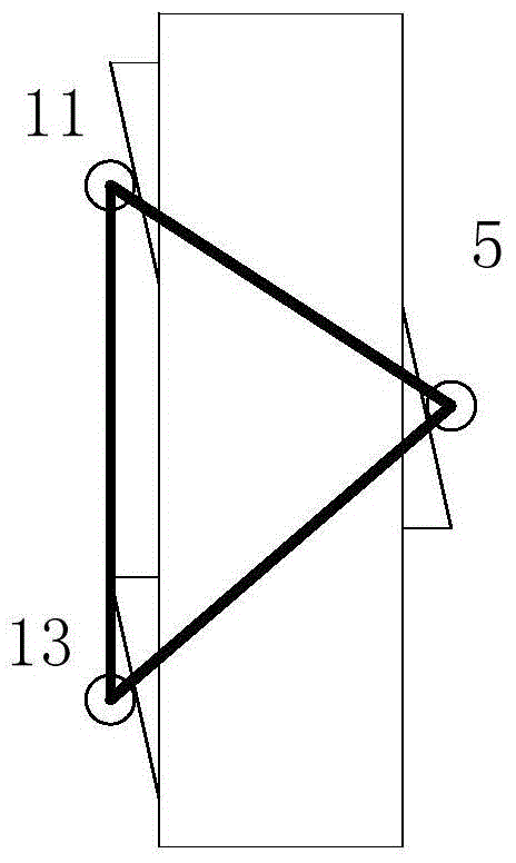
[0053] combine Figure 1-4 , a kind of slope guide rail shearing machine, it comprises pressure beam 6, upper blade 7, lower blade 9, knife rest 4 and feed support 14, the bottom of knife rest 4 is provided with upper blade 7, lower blade 9 and feed Support 14 is all arranged on the shearing machine platform, and the right side of knife rest 4 is provided with front guide rail 3, and the left side of knife rest 4 is provided with rear upper guide rail 10 and rear lower guide rail 12, and front guide rail 3 1. The angle between the guide rail surface of the rear upper guide rail 10 and the rear lower guide rail 12 and the tool holder 4 is α, the front guide rail 3 is connected with the front roller 5 arranged on the left side of the binder beam 6, and the rear upper roller The wheel 11 and the rear lower roller 13 move simultaneously. The rear upper roller 11 and the rear lower roller 13 move at the same time, so that the knife rest 4 does not rotate, but only moves in the ver...

Embodiment 2

[0073] Such as figure 1 , in this embodiment, a kind of slope guide rail shearing machine is installed with a camera in the cutting site workshop and connected with the controller. The controller saves the data captured by the camera and displays it in real time on the man-machine interface. The structure is the same Embodiment 1, a kind of shearing method of inclined-plane guide rail shearing machine, its steps are:

[0074] A, build described a kind of inclined-plane guide rail shearing machine, set and keep vertical between upper blade 7 and lower blade 9;

[0075] B. Input the thickness value of the plate to be cut into the man-machine interface, the controller sets the slope of the guide rail surface to 1:0.06 according to the thickness value of the plate, and calculates the horizontal gap between the upper blade 7 and the lower blade 9 set value;

[0076] C. The controller adjusts the slope of the guide rail surface to 1:0.06;

[0077] The following steps are the same...

Embodiment 3

[0079] This embodiment is the same as Embodiment 2, wherein the slope of the guide rail surface is 1:0.08.


PUM


Abstract

The invention discloses a bevel guide rail plate-shearing machine and a shearing method thereof and belongs to the field of mechanical manufacturing. The bevel guide rail plate-shearing machine comprises a material pressing beam, an upper knife blade, a lower knife blade, a knife rest and a feeding bracket. The upper knife blade is arranged on the lower portion of the knife rest. The lower knife blade and the feeding bracket are both arranged on a plate-shearing machine platform. A front guide rail is arranged on the right side surface of the knife rest. A back upper guide rail and a back lower guide rail are arranged on the left side surface of the knife rest. The included angle between the guide rail surface of the front guide rail and the knife rest, the included angle between the guide rail surface of the back upper guide rail and the knife rest and the included angle between the guide rail surface of the back lower guide rail and the knife rest are angles alpha, controlled by a controller and adjustable. The slope range of the guide rail surfaces is 0.06-0.08 mm. The front guide rail is connected with a front rolling wheel arranged on the left side surface of the material pressing beam. A back upper rolling wheel and a back lower rolling wheel move simultaneously and are both eccentric wheels. According to the bevel guide rail plate-shearing machine and the shearing method thereof, the perpendicularity and gap value between an upper knife and a lower knife can be automatically adjusted, and machining errors are small.

Description

technical field [0001] The invention relates to a hydraulic gate type shearing machine, which belongs to the field of mechanical manufacturing, and more specifically relates to a slope guide rail shearing machine and a shearing method thereof. Background technique [0002] At present, the angle structure between the moving surface of the tool holder on the mainstream shearing machine and the knife-edge surface is between 0.5 degrees and 1 degree. Such a structure is prone to processing errors during production and processing, and the two oil cylinders cannot be guaranteed to be on the same processing surface. Inside, it is generally corrected manually in the later stage, which will cause distortion and deformation of the shearing machine during the working process, which will affect the seal of the oil cylinder. During the shearing process, the upper knife and the lower knife will not interfere, but the impact The verticality of the upper knife and the lower knife is further...

Claims


Application Information

Patent Timeline
Patent Type & Authority Applications(China)
IPC IPC(8): B23D15/08B23D15/14B23D35/00
CPCB23D15/08B23D15/14B23D35/005
Inventor 许齐宝陈达兵王勇黄长连于珺余志钢
Owner 马鞍山市中亚机床制造有限公司
Why Eureka
Try Eureka