Wheel type pneumatic energy storage coke removing machine
What is AI technical title?
AI technical title is built by Patsnap AI team. It summarizes the technical point description of the patent document.
A coke machine and wheel-type technology, applied in the direction of lighting and heating equipment, etc., to achieve smooth focusing, stable and reliable fixing effect
Inactive Publication Date: 2016-08-03
HUNAN DATANG ENERGY SAVING SCI & TECH CO LTD
View PDF5 Cites 2 Cited by
Summary
Abstract
Description
Claims
Application Information
AI Technical Summary
This helps you quickly interpret patents by identifying the three key elements:
Problems solved by technology
Method used
Benefits of technology
Problems solved by technology
At present, there is no research and development of this product in China. In order to solve the problem of safe decoking of coal-fired boilers
Method used
Image
Click on the blue label to locate the original text in one second.
Reading with bidirectional positioning of images and text.
Examples
specific Embodiment approach 1
[0038] The present invention will be described in detail below in conjunction with the accompanying drawings. As attached to the manual figure 1 , 2 , as shown in 3:
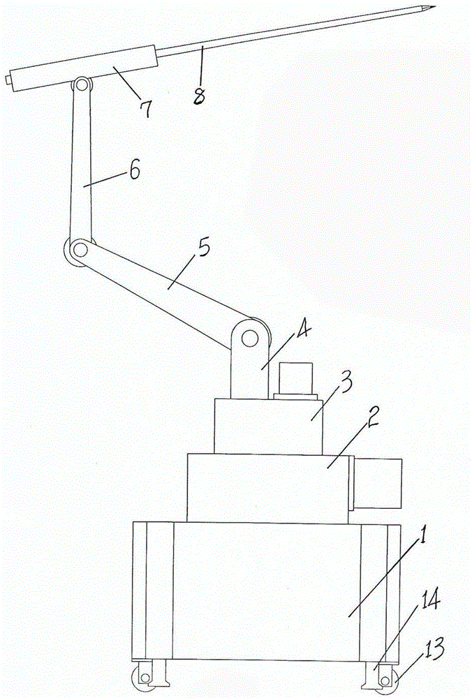
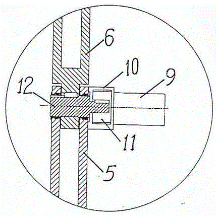
[0039] A wheel-type pneumatic energy storage coking machine, which consists of a frame plate 1, a rotating body 2, a frame body 3, a lifting arm 4, a main arm 5, a linkage arm 6, an air punching part 7, a steel braze 8, a gear motor 9, and a deceleration arm. Device 10, reduction gear 11, rotating shaft 12, driving wheel 13, support 14, crawler belt 15 constitute;
[0040] The wheel-type pneumatic energy storage coke machine, the bottom end of its frame plate 1 is connected with the drive wheel 13 in a rotating and flexible manner, its frame plate 1 is fixedly connected with the pneumatic device, and the output end of the pneumatic device is connected to the The upper end of the support 14 is fixedly connected, and the circular gear on the frame plate 1 is engaged with the circular gear on the transmission ou...
specific Embodiment approach 2
[0054] Implement on the basis of the implementation of the specific embodiment one, just as the description attached figure 1 , 2 Shown:
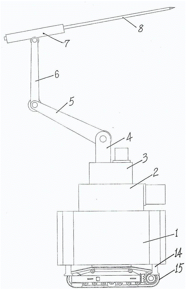
[0055] A wheel-type pneumatic energy storage coking machine, which consists of a frame plate 1, a rotating body 2, a frame body 3, a lifting arm 4, a main arm 5, a linkage arm 6, an air punching part 7, a steel braze 8, a gear motor 9, and a deceleration arm. Device 10, reduction gear 11, rotating shaft 12, drive wheel 13, support 14 constitute;
[0056] The wheel-type pneumatic energy storage coke machine, the bottom end of its frame plate 1 is connected with the drive wheel 13 in a rotating and flexible manner, its frame plate 1 is fixedly connected with the pneumatic device, and the output end of the pneumatic device is connected to the The upper end of the support 14 is fixedly connected, and the circular gear on the frame plate 1 is engaged with the circular gear on the transmission output shaft connected to the rotary motor on the r...
specific Embodiment approach 3
[0063] Carry out implementation on the basis of the implementation of specific implementation mode 1 and 2, just as the description attached figure 1 , 2 As shown, it is just that: replacing the pneumatic impact part 7 with a hydraulic impact device, the pneumatic energy storage is converted into hydraulic energy storage, and the wheel-type pneumatic energy-storage coking machine is converted into wheel-type hydraulic energy storage. Coking machine, thus producing the second extended new product of coking machine. The wheel-type hydraulic energy storage coking machine is equipped with a visual system, electrical control components and a remote remote controller. The operator can observe the real-time status of the working surface through the display on the control cabinet in the safe area, adjust the position of the brazing and automatically Carry out decoking operations. Good results were obtained as expected.
PUM
Abstract
The invention discloses a wheel type pneumatic energy storagecoke removing machine, and relates to the technical field of machinery. The key technology of driving wheel walking pneumatic or hydraulic energy storage or caterpillar band walking pneumatic or hydraulic energy storage is adopted. The wheel type pneumatic energy storage coke removing machine is characterized in that the bottom end of a frame plate is rotatably and movably connected with driving wheels; the frame plate is fixed to a pneumatic device; an output end of the pneumatic device is fixed to the upper ends of supports; an annular gear on the frame plate is in occlusion with a circular gear on an output shaft of a gearbox connected with a rotating motor on a rotating body; an annular rail on the frame plate is movably connected with a rail wheel of the lower end of the rotating body in a rolling manner; the upper end of the rotating body is fixed to the lower end of a frame body; the frame body is fixed to the pneumatic device; the output end of the pneumatic device is fixed to a lifting arm; the upper end of the lifting arm and the lower end of a master arm, the upper end of the master arm and the lower end of a linkage arm, and the upper end of the linkage arm and a pneumatic part are rotatably and movably connected through deceleration motors; and an output end of the pneumatic part is fixed to the back end of a steel chisel. The wheel type pneumatic energy storage coke removing machine is used for removing cokes of a utility boiler, and is a new product which is simple and ingenious in structure, stable in effect, easy to manufacture, and low in cost.
Description
technical field [0001] The invention relates to a wheel-type pneumatic energy storage coking machine, which relates to the technical field of machinery; in particular, it relates to the technical field of a wheel-type pneumatic energy storage coking machine. Background technique [0002] Industrial large-scale coal-fired boilers will inevitably cause coking on the furnace wall and cold ash hopper during the combustion process, especially when using low-quality coal and high-sulfurcoal, the coking is more serious. If it is not removed, it will endanger the safe operation of the boiler. Although people add various anti-coking agents to coal, it is still impossible to completely avoid coking. The coke block has strong adhesion to the furnace wall surface, and usually cannot fall off by its own gravity, and must be removed by external force to make it fall off. The temperature of the coking part is 200-700°C, and the observation hole for decoking is relatively small, usually ...
Claims
Application Information
Patent Timeline
Application Date:The date an application was filed.
Publication Date:The date a patent or application was officially published.
First Publication Date:The earliest publication date of a patent with the same application number.
Issue Date:Publication date of the patent grant document.
PCT Entry Date:The Entry date of PCT National Phase.
Estimated Expiry Date:The statutory expiry date of a patent right according to the Patent Law, and it is the longest term of protection that the patent right can achieve without the termination of the patent right due to other reasons(Term extension factor has been taken into account ).
Invalid Date:Actual expiry date is based on effective date or publication date of legal transaction data of invalid patent.

