
Eureka
For R&D, Eureka makes reading and utilizing patents & technical documents easy.
Eureka AIR
Designed for self-driven R&D workflows. Generate viable solutions, solve complex R&D challenges, empower your innovation with AI.

Eureka Materials
Designed for material experts only. Revolutionize your material R&D, from search, analyze, to developing new materials.

TechResearch
Generate reliable direction feasibility study reports for your R&D in just a few steps.

TechSeek
Discover and master advanced knowledge NOW. Basics, ideas, possibilities, all at once.

TechMind
As an expert in R&D Theories, TechMind can generates customized viable solutions instantly.

TechRisk
Analyze your overall solution with one click, know your potential R&D risks in advance.

TechMonitor
Get weekly tech updates, stay abreast of the latest tech innovations and key insights.
Anti-off pin insulator
A pin-type insulator, anti-falling technology, applied in the direction of pin-type insulators, insulators, electrical components, etc., can solve the problems of high maintenance rate, poor safety, easy to fall off, etc., to achieve safe and stable power lines, reasonable and compact structure, Ease of use
- Summary
- Abstract
- Description
- Claims
- Application Information
AI Technical Summary
Problems solved by technology
Method used
Image

Examples
Embodiment 1
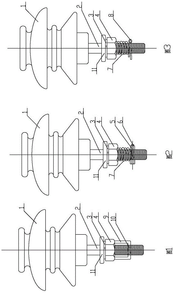
[0021] Embodiment 1: as attached figure 1 As shown, the above-mentioned locking nut limiting device includes a limit pin 10 and a strut 9, the limit pin 10 is located in the through hole of the insulating needle 2, and the two ends of the limit pin 10 are fixedly connected with the strut 9, and the strut 9 The upper end surface abuts against the lower end surface of the lock nut 4 . After installing and fixing the insulating pin 2, insert the limit pin 10 into the through hole at the lower part of the insulating pin 2, then bend the two ends and stand up to form two vertical struts 9 to ensure at least one vertical strut The upper end surface of 9 is against the lower end surface of lock nut 4, and the limit lock nut 4 loosens and moves down. The limit pin here can be made of metal material with high plasticity. According to needs, the two ends of the strut 9 and the limit pin 10 can be connected by snap-fitting or threading. The two ends of the limit pin 10 can be locked o...
Embodiment 2
[0022] Embodiment 2: as attached figure 2 As shown, the above lock nut limiting device includes a bolt 6, a limit nut 5 and a compression spring 7, the bolt 6 is fixed in the through hole of the insulating needle 2 through the limit nut 5, and the compression spring 7 is sleeved on the lock nut 4 and the insulating pin 2 between the bolt 6. After installing and fixing the insulating pin 2, set the compression spring 7 from the lower end of the insulating pin 2, press the compression spring 7 on the lower end surface of the lock nut 4, insert the bolt 6 into the through hole at the bottom of the insulating pin 2, and use it After the matching limit nut 5 fixes the bolt 6 on the lower part of the insulating needle 2, the compression spring 7 is released, and the compression spring 7 is in a compressed state between the lock nut 4 and the bolt 6, and an upward movement is given to the upper lock nut 4. thrust to prevent it from loosening and moving down.
Embodiment 3
[0023] Embodiment 3: as attached image 3 As shown, the above-mentioned lock nut limiting device includes a limiting clip 8 and a compression spring 7, the limiting clip 8 is fixed in the through hole of the insulating needle 2, and the compression spring 7 is sleeved between the limiting clip 8 and the bolt 6 Insulate on pin 2. After the insulating pin 2 is installed and fixed, the compression spring 7 is set from the lower end of the insulating pin 2, and after the compression spring 7 is pressed on the lower end surface of the lock nut 4, a limit clip 8 is installed in the through hole at the bottom of the insulating pin 2, Unclamp the compression spring 7, the compression spring 7 is in a compressed state between the lock nut 4 and the limit clip 8, and an upward thrust is given to the lock nut 4 above to prevent it from loosening and moving down.
[0024] According to actual needs, the above-mentioned anti-falling pin insulators can be further optimized or / and improved: ...
PUM
 Abstract
Description
Claims
Application Information
 - R&D Engineer
- R&D Manager
- IP Professional
- Industry Leading Data Capabilities
- Powerful AI technology
- Patent DNA Extraction
Browse by: Latest US Patents, China's latest patents, Technical Efficacy Thesaurus, Application Domain, Technology Topic, Popular Technical Reports.
© 2024 PatSnap. All rights reserved.Legal|Privacy policy|Modern Slavery Act Transparency Statement|Sitemap|About US| Contact US: help@patsnap.com