Line fixing mechanism

A technology of a wire fixing device and an auxiliary mechanism, which is applied in the installation of electrical components, cables, overhead installation, etc., can solve the problems of affecting the firmness and lasting effectiveness of wire clamping, cumbersome unlocking work, and inconvenient disassembly.

Active Publication Date: 2016-08-03
GUANGZHOU PANYU CABLE WORKS
View PDF5 Cites 12 Cited by
  • Summary
  • Abstract
  • Description
  • Claims
  • Application Information

AI Technical Summary

Problems solved by technology

The wire fixing device is not set to provide a fixed or connected pulling auxiliary mechanism for the cable pulling device. Although the cable can be fastened, the locking and anti-loosening are all based on the locking block. The loosening direction and the locking direction are two opposite directions similar to the straight line direction, and the part where the movable chuck and the locking block zigzag fits has relatively insufficient mechanical properties. When pulling or clamping cables, especially the fixed If the line device is far apart, the cable is thicker or at a corner, the movable chuck must bear a large tension, and the corresponding locking block is also subject to a large force. The matching parts of the two are easily damaged, which affects the firmness of the clamping line. And long-lasting effectiveness, the service life of the wire fixing device is limited, and the manual clamping head is directly turned in place, and the clamping head cooperates with the static chuck. It is not easy to clamp the cable, which may cause the fixed cable to shake. It is hoped that the wire fixing device will be removed from When the cable is removed and reused, the unlocking work is cumbersome and inconvenient to disassemble, which prolongs the aerial work time of the construction personnel

Method used


Image

  • Line fixing mechanism
  • Line fixing mechanism
  • Line fixing mechanism

Examples


Embodiment 1

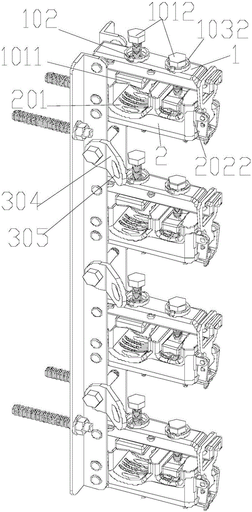
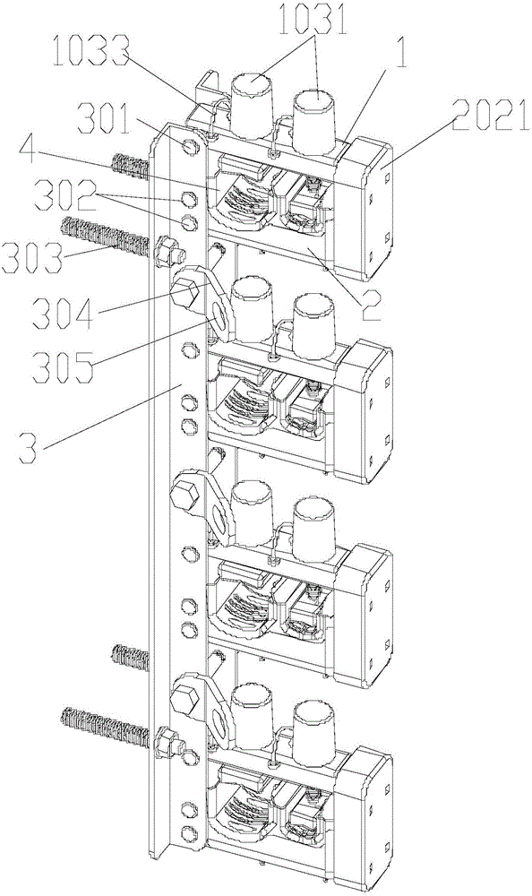
[0042] Such as Figure 1-6 As shown, a wire fixing mechanism includes a wire fixing device, the wire fixing device includes a base 3 and four wire passing devices arranged on the base 3, and a traction auxiliary mechanism arranged on the base 3 for connecting the cable pulling device .

[0043] The traction auxiliary mechanism includes three traction plates 304 which are fixedly connected with the base 3 , and each traction plate 304 is provided with a traction hole 305 .

[0044] The way that the traction plate 304 is fixedly connected to the base 3 is a detachable fixed connection through bolts.

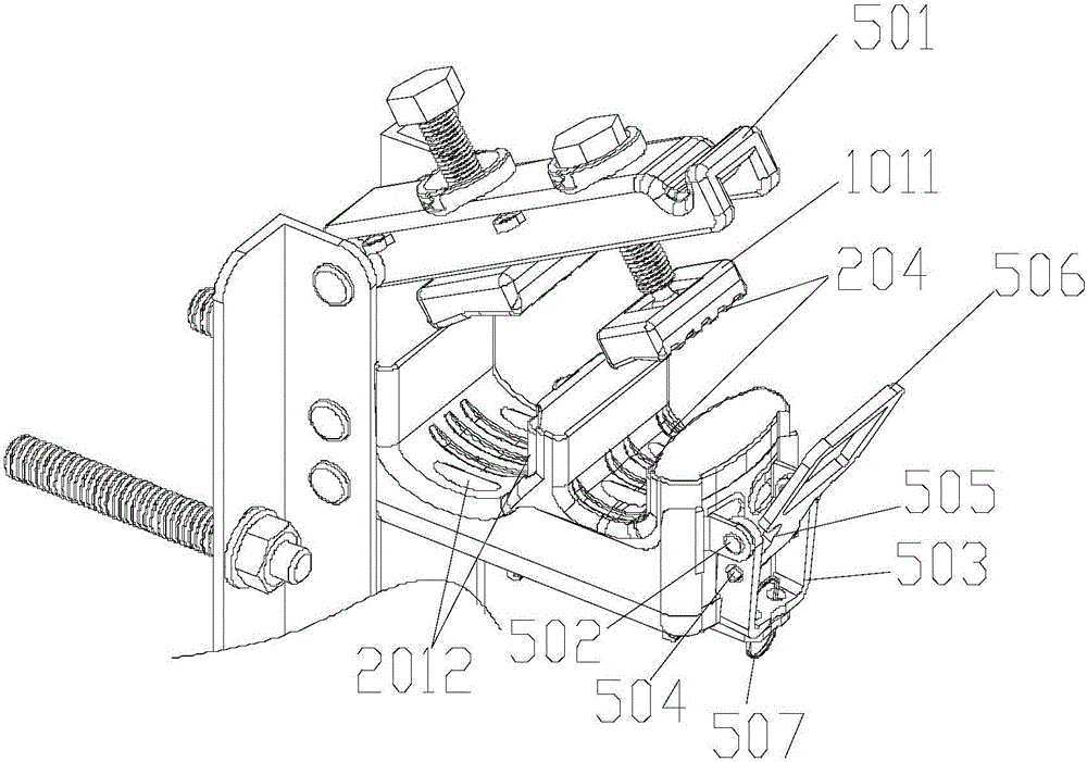
[0045] Each wire passing device includes a pair of first body 1 and second body 2, one end of the first body 1 is fixedly connected to the base 3, one end of the second body 2 is hinged to the base 3 through the first hinge shaft 301, and the second The other end of a body 1 is detachably connected to the other end of the second body 2; each first body 1 is provided with two clam...

Embodiment 2

[0069] On the basis of the technical solution of the wire fixing mechanism in embodiment 1, the following improvements have been further made:

[0070] Such as Figure 1-6 As shown, a first protective cover 1031 for protecting the locking bolt 1012 is also provided on the first body 1 .

[0071] The first body 1 is also provided with a first buckle device that cooperates with the first protective cover 1031 .

[0072] The first locking device is a rotating buckle 1032 provided on the flange surrounding the locking hole 102 . During use, the first protective cover 1031 can be locked or opened with the rotating buckle 1032 by rotating it.

[0073] The first protective cover 1031 is connected to the first main body 1 through a first connecting wire 1033 , one end of the first connecting wire 1033 is fixed on the first protective cover 1031 , and the other end is fixed on the first main body 1 .

[0074] The wire fixing mechanism is also provided with a second protective cover 2...


PUM


Abstract

The invention discloses a line fixing mechanism. The line fixing mechanism includes a line fixing device and traction assisting mechanisms arranged on the line fixing device; each traction assisting mechanism comprises traction holes for connecting or fixing cable traction devices; the line fixing device comprises a base and line passing devices, wherein each line passing device is arranged on the base and includes a first body and a second body; the first body and the second body are provided with line clamping heads and line clamping portions respectively, wherein the line clamping heads can be matched with the line clamping portions, so that line passing spaces can be formed; each line clamping head includes a locking bolt and a line clamping block; the locking bolt is rotatably connected with the line clamping block; the locking bolt is connected with the first body through a screw hole; and when the line fixing mechanism is used, the locking bolt is rotated so as to drive the corresponding line clamping block to move, so that the size of the corresponding line passing space can be adjusted. The line fixing mechanism of the invention has the advantages of simple structure, waterproof, damp-proof and anti-oxidation performance, high security, stable cable clamping, long service life and easiness in disassembly.

Description

technical field [0001] The invention relates to the field of cable installation, in particular to a wire fixing mechanism. Background technique [0002] It is very important to ensure the safe and stable operation of the power grid. If the wire connection is not properly handled, it will bring a lot of troubles to people's production and life, and even affect safety. For cable or wire connections that require high-altitude operations, whether the installation and removal of the cable fixing device is convenient will directly affect the length of the aerial work time. If it is not convenient, it will increase the high-altitude operation time and increase the construction risk. Disposal, maintenance and reuse, and whether the wire connection is safe and reliable, is related to people's personal safety, and needs special attention. [0003] The wire fixing device is a device used to straighten and fix the cable. In the process of straightening and fixing the cable, the cable p...

Claims


Application Information

Patent Timeline
Patent Type & Authority Applications(China)
IPC IPC(8): H02G7/05
CPCH02G7/053
Inventor 胡超强尤占山王延发覃丹卢广业张仕欢陈雪儿郝燕张开拓易坡杜小建程雪丽
Owner GUANGZHOU PANYU CABLE WORKS
Why Eureka
Try Eureka