
A vector diagram analysis method of virtual impedance of inverter

A technology of virtual impedance and analysis method, which is applied to the conversion device of output power, the conversion of AC power input to DC power output, complex mathematical operations, etc.

Active Publication Date: 2019-06-28
东台城东科技创业园管理有限公司
View PDF5 Cites 0 Cited by
  • Summary
  • Abstract
  • Description
  • Claims
  • Application Information

AI Technical Summary

Problems solved by technology

However, the analysis with the Bode diagram can only observe how the equivalent output impedance of the inverter changes, and cannot explain the reason for this change.
In addition, different types of virtual impedances added have different effects on the output impedance of the inverter, and Bode diagram analysis cannot conveniently prompt the type and size of virtual impedances that need to be introduced

Method used


Image

  • A vector diagram analysis method of virtual impedance of inverter
  • A vector diagram analysis method of virtual impedance of inverter
  • A vector diagram analysis method of virtual impedance of inverter

Examples


Embodiment Construction

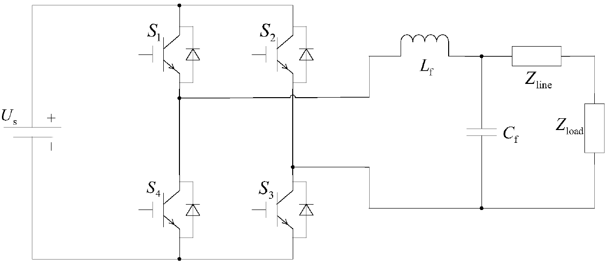
[0036] The vector diagram analysis method of a kind of inverter virtual impedance of the present invention comprises the following steps:

[0037] Step 1, list the corresponding transfer function through the control block diagram of the inverter;

[0038] Step 2, set s=jω in the transfer function, and calculate the original output impedance of the inverter at the fundamental frequency;

[0039] Step 3, add the virtual impedance, and list the corresponding transfer function through the control block diagram after adding the virtual impedance;

[0040] Step 4, set s=jω in the transfer function of step 3, and calculate the equivalent output impedance of the inverter at the fundamental frequency;

[0041] Step 5, draw an orthogonal coordinate system with the vertical axis as an imaginary number and the horizontal axis as a real number;

[0042] Step 6, draw the vector corresponding to the original output impedance;

[0043] Step 7, draw the vector corresponding to the amount of...


PUM


Abstract

The invention provides an inverter virtual impedance vector diagram analysis method. The size and nature of output impedance at the fundamental frequency of an inverter are analyzed under different types of virtual impedances added. By introducing virtual impedance, the size and nature of the original output impedance of an inverter can be changed, and an inverter output impedance can be acquired as needed. A virtual impedance module is added on the basis of the original voltage and current double-closed-loop feedback control system. The adopted current feedback is inductive current feedback. Thus, the change in output impedance at the fundamental frequency of an inverter under five conditions, namely, adding virtual positive inductance, adding virtual negative inductance, adding virtual positive resistance, adding virtual negative resistance, and adding virtual complex impedance composed of virtual positive resistance and virtual negative inductance, can be analyzed and verified based on a vector diagram and a corresponding Bode diagram.

Description

technical field [0001] The invention relates to a control system of an inverter. Background technique [0002] In the control system of the inverter, the output impedance of the inverter can be changed to become purely resistive or purely inductive, so as to achieve the purpose of decoupling the active power and reactive power of the inverter. The method of introducing virtual impedance is realized. Nowadays, the analysis of the introduced virtual impedance is usually carried out by means of Bode plots. [0003] The Bode diagram can clearly see the change of the equivalent output impedance of the inverter after adding different types of virtual impedance in the whole frequency domain, which is especially obvious in the low frequency band. However, analyzing with the Bode diagram can only observe how the equivalent output impedance of the inverter changes, and cannot explain the reason for this change. In addition, different types of virtual impedances added have different...

Claims


Application Information

Patent Timeline
Patent Type & Authority Patents(China)
IPC IPC(8): H02J3/46H02M7/5387G06F17/15
CPCG06F17/15H02J3/46H02M7/5387
Inventor 刘国海姜宇珺陈兆岭顾雪珂
Owner 东台城东科技创业园管理有限公司
Learn More