Visible light communication positioning system and method

A technology of visible light communication and positioning system, applied in the field of visible light communication positioning system, can solve the problems of affecting positioning accuracy, GPS positioning cannot be applied to indoor positioning, interference, etc., and achieve the effect of high positioning accuracy

Inactive Publication Date: 2016-08-03
THE PLA INFORMATION ENG UNIV
View PDF6 Cites 18 Cited by
  • Summary
  • Abstract
  • Description
  • Claims
  • Application Information

AI Technical Summary

Problems solved by technology

However, GPS positioning cannot be applied to indoor positioning
Although Wi-Fi positioning can be applied to indoor and outdoor positioning, it is susceptible to interference from other radio signals, which affects positioning accuracy

Method used


Image

  • Visible light communication positioning system and method
  • Visible light communication positioning system and method
  • Visible light communication positioning system and method

Examples


Embodiment 1

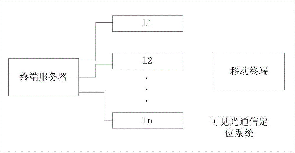
[0052] See figure 1 , Which shows a schematic diagram of a logical structure of the visible light communication positioning system provided by the present application. The visible light positioning system includes a terminal server, at least one mobile terminal and multiple visible light signal sources. in figure 1 In the figure, multiple visible light signal sources are denoted as L1, L2, ..., Ln.

[0053] In this embodiment, the ID (identity identification number) address of each visible light signal source is different.

[0054] The terminal server is respectively connected to each of the visible light signal sources.

[0055] Each visible light signal source is used to transmit a visible light signal carrying its own ID.

[0056] The mobile terminal is configured to receive the visible light signal emitted by the visible light signal source corresponding to the visible light coverage area where it is located, convert the received visible light signal into a first electrical signal...

Embodiment 2

[0085] In an embodiment, a visible light communication positioning method is provided, which is based on a visible light communication positioning system. The visible light communication positioning system includes a terminal server, a mobile terminal, and multiple visible light signal sources. The ID of each visible light signal source is different. Similarly, the terminal server is respectively connected to each of the visible light signal sources, and the terminal server is configured to assign different IDs to each of the visible light signal sources.

[0086] See Figure 5 , Which shows a flow chart of the visible light communication positioning method provided by this application, which may include the following steps:

[0087] Step S51: Each of the visible light signal sources respectively emits a visible light signal carrying its own ID.

[0088] In this embodiment, the process of each of the visible light signal sources respectively emitting visible light signals carrying t...


PUM


Abstract

The invention provides a visible light communication positioning system and method. The visible light communication positioning system comprises visible light signal sources each used for sending a visible light signal which carries an ID thereof; a mobile terminal used for receiving the visible light signal sent by one visible light signal source which corresponds to a visible light coverage region where the mobile terminal is, converting the received visible light signal into a first electric signal and sending the first electric signal to a terminal server; and the terminal server used for analyzing the ID from each first electric signal, regarding the coverage region of each visible light signal source which corresponds to the ID analyzed from each first electric signal as a position region of the mobile terminal and displaying the position region of the mobile terminal. No matter indoors or outdoors, positioning can be realized as long as the visible light signal source (such as an electric lamp) exists. The visible light signals cannot be interfered by other radio signals in the positioning process; and the positioning precision is relatively high.

Description

Technical field [0001] This application relates to the field of mobile positioning, and in particular to a visible light communication positioning system and method. Background technique [0002] In recent years, with the increase in user demand, the application of mobile positioning technology has become more and more extensive. Among them, mobile positioning technology can be used to locate people, events, and objects to meet the positioning needs of industries such as emergency rescue and help, mobile law enforcement, mobile office, transportation, logistics, tourism, and land resources investigation. [0003] The current mobile positioning methods mainly include GPS positioning and Wi-Fi (Wireless-Fidelity, wireless network) positioning. However, GPS positioning cannot be applied to indoor positioning. Although Wi-Fi positioning can be applied to indoor and outdoor positioning, it is susceptible to interference from other radio signals and affects positioning accuracy. Summa...

Claims


Application Information

Patent Timeline
Patent Type & Authority Applications(China)
IPC IPC(8): H04B10/116H04B10/516G01S11/12
CPCH04B10/116G01S11/12H04B10/516
Inventor 汪涛刘潇忆朱义君于宏毅邬江兴张剑田忠骏仵国锋张效义张霞
Owner THE PLA INFORMATION ENG UNIV
Why Eureka
Try Eureka