Integral dropper pressing mold

A crimping die and overall technology, applied in the field of electrified railway catenary equipment, can solve problems such as no direction requirements, broken wires and strands, affecting line safety, etc., and achieve the effect of avoiding loose strands, avoiding wear and tear, and less wear

Inactive Publication Date: 2016-08-10
宝鸡保德利电气设备有限责任公司
View PDF11 Cites 0 Cited by
  • Summary
  • Abstract
  • Description
  • Claims
  • Application Information

AI Technical Summary

Problems solved by technology

[0003] The technical problem solved by the present invention is to design an integral hanging string crimping die, change the structure of the original 1-2 teeth asymmetrical crimping die, and adopt a crimping groove with a larger force-bearing area to improve the service life of the die. Direction requirements, solve the problem of broken wires and strands affecting line safety due to crimping damage during the operation of the overall suspension line of electrified railways

Method used


Image

  • Integral dropper pressing mold
  • Integral dropper pressing mold
  • Integral dropper pressing mold

Examples


Embodiment Construction

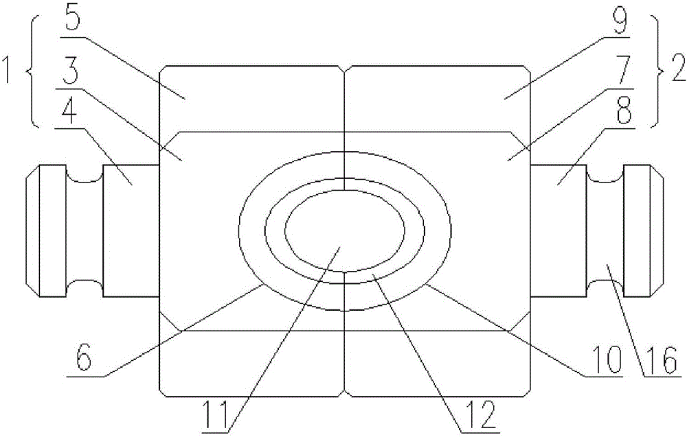
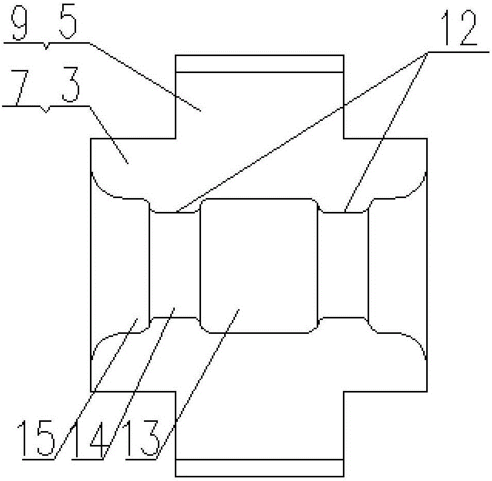
[0017] combined with Figure 1-5 An embodiment of the present invention is described.

[0018] An integral hanging string crimping die, the crimping die includes a symmetrically matched sub-mold I1 and a sub-mold II2, the sub-mold I1 includes a sub-mold body I3, a connecting column I4 formed at the end of the sub-mold body I3 and a separate The guide block I5 on both sides of the sub-mold body I3, the sub-mold body I3 is formed with a mold cavity I6; the sub-mold II2 includes the sub-mold body II7, the connecting column II8 formed at the end of the sub-mold body II7 and the The guide block II9 on both sides of the sub-mold body II7, the sub-mold body II7 is formed with a mold cavity II10, the mold cavity I6 and the mold cavity II10 are enclosed to form an elliptical crimping hole 11, and two symmetrically arranged inside the mold cavity The ring-shaped boss 12, the ring-shaped boss 12 divides the oval crimping hole 11 into a receiving section 13 located in the middle, a crimp...


PUM


Abstract

The invention discloses an integral dropper pressing mold. The pressing mold comprises a sub mold I and a sub mold II symmetrically matched; the sub mold I includes a sub mold body I, a connecting column I formed at the end part of the sub mold body I, and guide blocks I respectively arranged on two sides of the sub mold body I; a mold cavity I is formed in the sub mold body I; the sub mold II includes a sub mold body II, a connecting column II formed at the end part of the sub mold body II, and guide blocks II respectively arranged on two sides of the sub mold body II; a mold cavity II is formed in the sub mold body II; the mold cavity I and the mold cavity II define an elliptic pressing hole; and two annular bosses are symmetrically arranged in the mold cavity. The integral lifting chord pressing mold changes a traditional 1-2-tooth asymmetric pressing mold structure, adopts a pressing groove with a larger stress area, prolongs the service life, has no direction requirements in use, and solves the problem of influence on the circuit safety by wire and strand breakage caused by pressing damage in the integral dropper circuit operation process of an electric railway.

Description

technical field [0001] The invention relates to the technical field of catenary equipment for electrified railways, in particular to an integral hanging string crimping mold. Background technique [0002] As one of the important components in the electrified railway catenary, the integral suspension string is also the main suspension part, which plays a vital role in the electrified railway catenary. At present, the integral suspension strings used in the electrified railway catenary, and the suspension string crimping tubes are mostly crimped with pointed dog-tooth molds, that is, the 1-2 teeth at the crimping tube are asymmetrically crimped, and the force and deformation of the two tooth sides It is 1 / 2 of the single tooth, mainly relying on the crimping method of point or line contact, so that the stress is concentrated during crimping, the axial force is uneven, the stranded wire is bent, and an additional bend is formed at the outlet of the crimping point. moment, resu...

Claims


Application Information

Patent Timeline
IPC IPC(8): B21F15/00
CPCB21F15/00
Inventor 黄婷闫军芳李军杰李永生杨团厚
Owner 宝鸡保德利电气设备有限责任公司
Why Eureka
Try Eureka