
Glasses leg polishing machine

A technology for spectacle temples and polishing machines, which is applied to surface polishing machine tools, grinding/polishing equipment, conveyors, etc., and can solve the problems of reduced production efficiency and low production efficiency

Active Publication Date: 2016-08-10
温州创宇智能设备有限公司
View PDF7 Cites 6 Cited by
  • Summary
  • Abstract
  • Description
  • Claims
  • Application Information

AI Technical Summary

Problems solved by technology

[0002] In order to make the spectacle feet of the spectacle frame can be further bent during use to prolong the service life of the spectacle frame, the spectacle legs are composed of spectacle leg plastic parts and spectacle pin pins, and usually insert a spectacle pin pin into the spectacle plastic parts Needles and temples are an important part of glasses. The temples are usually polished before painting and assembly. Polishing mainly involves friction between the temples and the polishing wheel to remove the burrs on the surface of the temples and make the outer surface of the temples smooth. A process that is convenient for painting, usually manually take the temples of the glasses close to the polishing wheel for polishing, the production efficiency is low, and the production efficiency is reduced

Method used


Image

  • Glasses leg polishing machine
  • Glasses leg polishing machine
  • Glasses leg polishing machine

Examples


Embodiment Construction

[0021] Refer to attached Figure 1 to Figure 4 A spectacle temple polishing machine of the present invention is described in further detail.

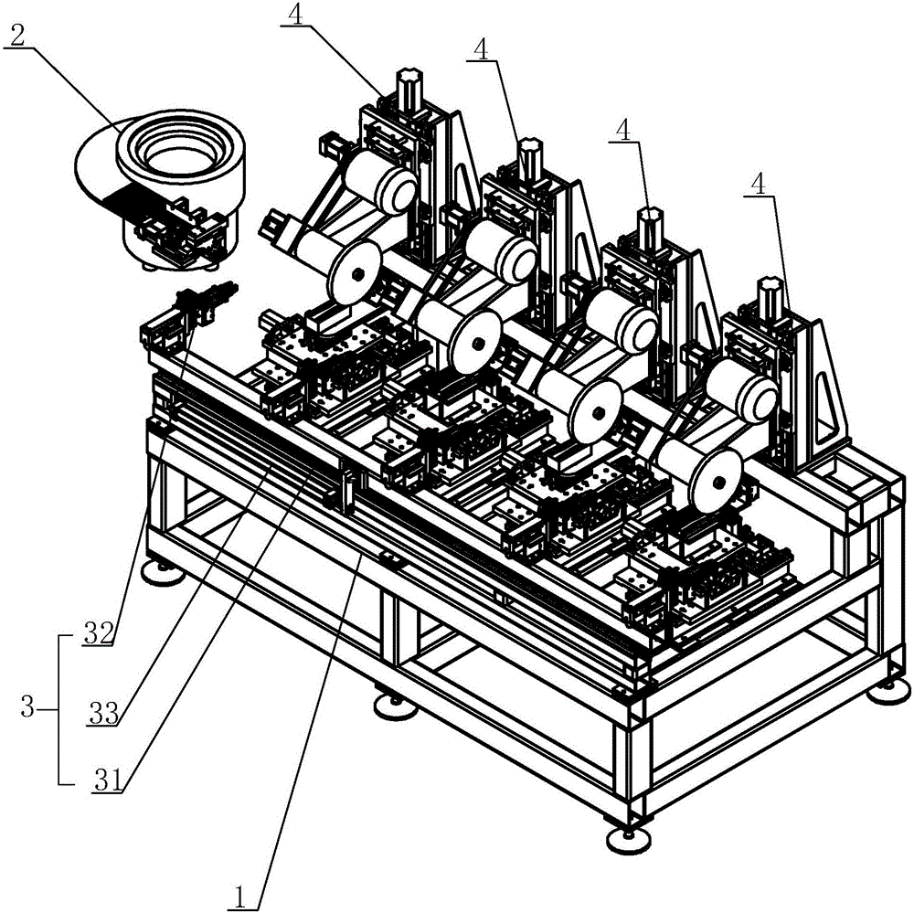
[0022] A spectacle temple polishing machine, comprising a frame 1, the frame 1 is provided with a feeding mechanism 2, a conveying mechanism 3 and several polishing mechanisms 4, and the conveying mechanism 3 includes a conveying track 31 and several conveying Manipulator 32 on track 31, described conveying track 31 is provided with and drives the conveying driver 33 of manipulator 32 reciprocating slide; Described feeding mechanism 2 is arranged on the side of conveying track 31, and several polishing mechanisms 4 are distributed along conveying track 31 intervals; The number of polishing mechanisms 4 can be determined according to actual conditions.

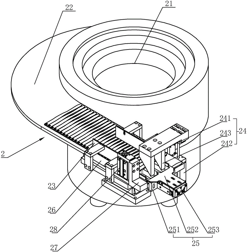
[0023] The feeding mechanism 2 includes a vibrating plate 21, the discharge port of the vibrating plate 21 is provided with a feeding channel 22, and the top of the feeding channel 22 i...


PUM


Abstract

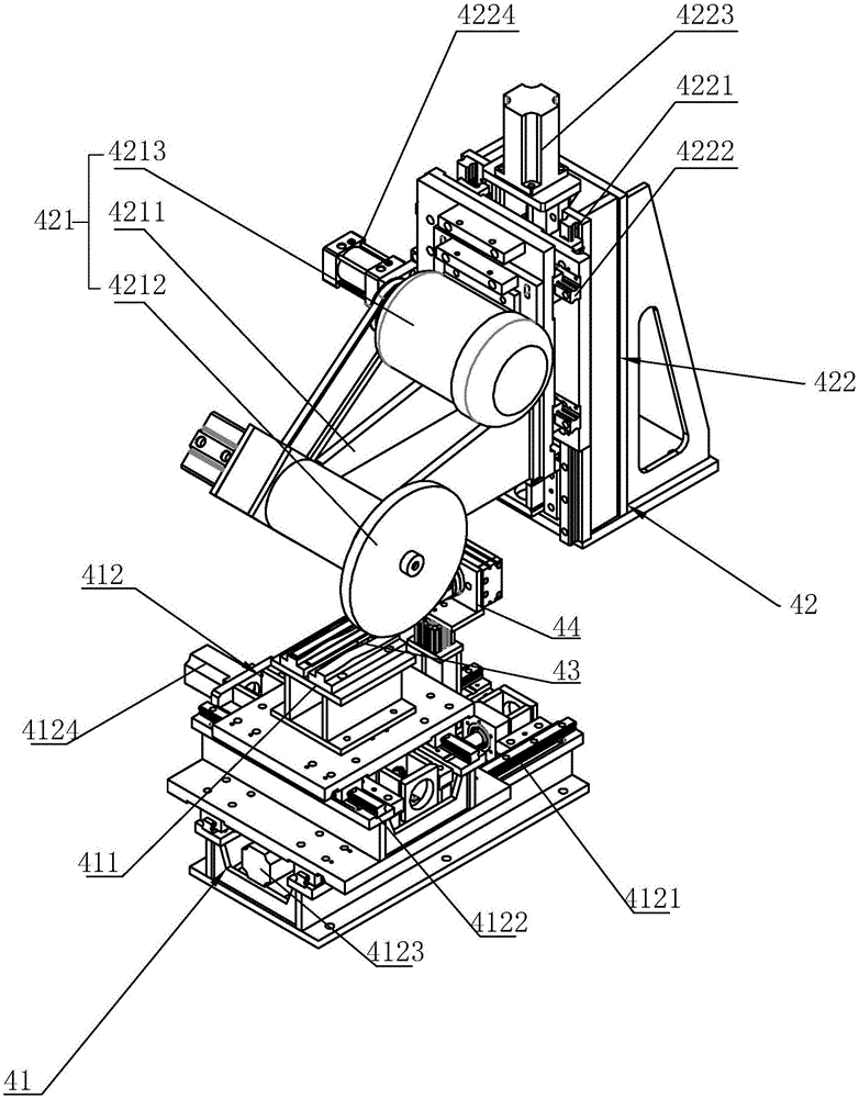
The invention discloses a glasses leg polishing machine. A feeding mechanism, a conveying mechanism and a plurality of polishing mechanisms are arranged on a machine frame. The conveying mechanism comprises a conveying track and a plurality of mechanical arms arranged on the conveying track. A conveying driver for driving the mechanical arms to do reciprocating sliding is arranged on the conveying track. The feeding mechanism is arranged on one side of the conveying track. The polishing mechanisms are distributed at intervals along the conveying track. Each polishing mechanism comprises a clamping device for clamping a glasses leg and a polishing device used for polishing the glasses leg. Each clamping device comprises a carrying platform used for carrying the glasses leg and a carrying platform moving assembly used for driving the carrying platform to move relative to a polishing wheel assembly. One side of each carrying platform is provided with a clamping arm used for clamping the glasses leg and a clamping arm moving assembly used for driving the clamping arm to rotate and move relative to the corresponding carrying platform. Each polishing wheel assembly is arranged above the corresponding carrying platform. The glasses leg polishing machine achieves the effect of automatic polishing and improves the production efficiency.

Description

technical field [0001] The invention relates to the field of mechanical equipment, more specifically, it relates to a spectacle temple polishing machine. Background technique [0002] In order to make the spectacle feet of the spectacle frame can be further bent during use to prolong the service life of the spectacle frame, the spectacle legs are composed of spectacle leg plastic parts and spectacle pin pins, and usually insert a spectacle pin pin into the spectacle plastic parts Needles and temples are an important part of glasses. The temples are usually polished before painting and assembly. Polishing mainly involves friction between the temples and the polishing wheel to remove the burrs on the surface of the temples and make the outer surface of the temples smooth. A process that is convenient for painting, usually manually takes the temples of the glasses close to the polishing wheel for polishing, which has low production efficiency and reduces production efficiency. ...

Claims


Application Information

Patent Timeline
IPC IPC(8): B24B29/02B24B41/02B24B41/06B65G47/28B65G27/00B25J9/00
CPCB24B29/02B24B41/02B24B41/06B25J9/00B65G27/00B65G47/28B65G2201/0217
Inventor 郑能健诸国光
Owner 温州创宇智能设备有限公司
Learn More