Sand mold printing equipment and printing method

A technology of printing equipment and casting molds, which is applied in the direction of casting molding equipment, metal processing equipment, casting molds, etc., can solve the problems of slow printing speed, achieve the effects of increasing molding speed, avoiding excessive curing agent content, and shortening printing time

Inactive Publication Date: 2018-01-30
SHANGHAI JIAO TONG UNIV
View PDF6 Cites 0 Cited by
  • Summary
  • Abstract
  • Description
  • Claims
  • Application Information

AI Technical Summary

Problems solved by technology

In this technology, the nozzles are fixedly arranged in a dot matrix, the nozzles are in a two-axis motion printing mode, and the printing platform performs two-dimensional motion. In essence, it still uses dot molding for molding movement, and the printing speed is relatively slow.

Method used


Image

  • Sand mold printing equipment and printing method
  • Sand mold printing equipment and printing method
  • Sand mold printing equipment and printing method

Examples


Embodiment 1

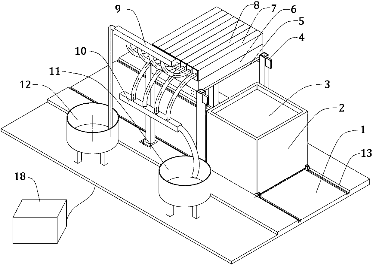
[0031] Such as figure 1 As shown, this embodiment includes: base 1, forming box car 2, blanking support 4, selective paving mechanism 5, blanking mechanism 6, molding material upper hopper 7, auxiliary molding material upper hopper 8, auxiliary molding material The conveying mechanism 9, the molding material conveying mechanism 10 and the control unit 18, wherein: the base 1 is provided with a guide rail 13, the printing platform 3 is movable up and down in the forming box car 2, the forming box car 2 is movably connected with the guide rail 13, and the blanking support 4 Erected on the top of the guide rail 13 and fixedly connected with the base 1, the selective laying mechanism 5 and the blanking mechanism 6 are fixed on the blanking support 4 in sequence from bottom to top, and the molding material upper hopper 7 and the auxiliary molding material upper hopper 8 Alternately arranged on the blanking mechanism 6, the auxiliary molding material conveying mechanism 9 and the mo...

Embodiment 2

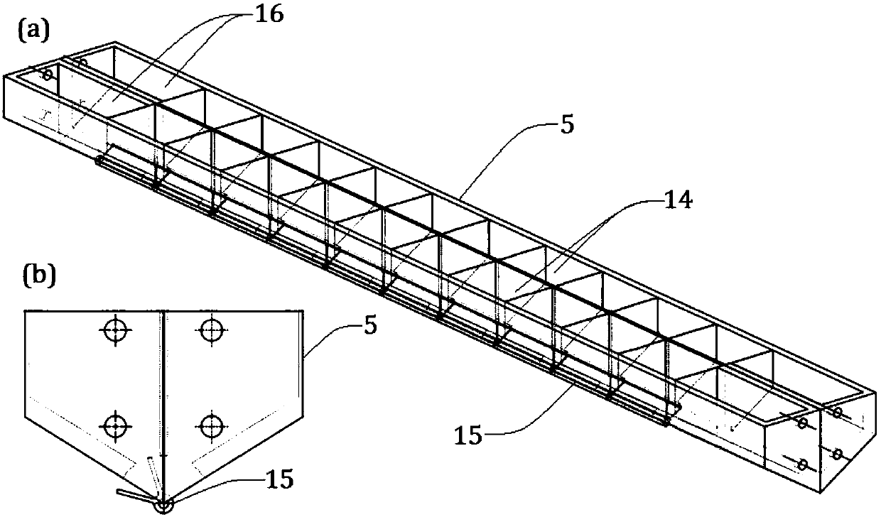
[0046] The difference from Example 1 is that, as image 3 As shown, the selective paving mechanism 5 is wide at the top and narrow at the bottom, and the bottom is wedge-shaped and provided with convex nozzles 17. The nozzle switch 15 is a linear motor switch and is alternately arranged on both sides of the convex nozzles 17; When the nozzle switch 15 is working, it can block any side of the convex nozzle 17 to realize the falling of the material on the other side, and then realize the selective laying of the molding material and the auxiliary molding material.

Embodiment 3

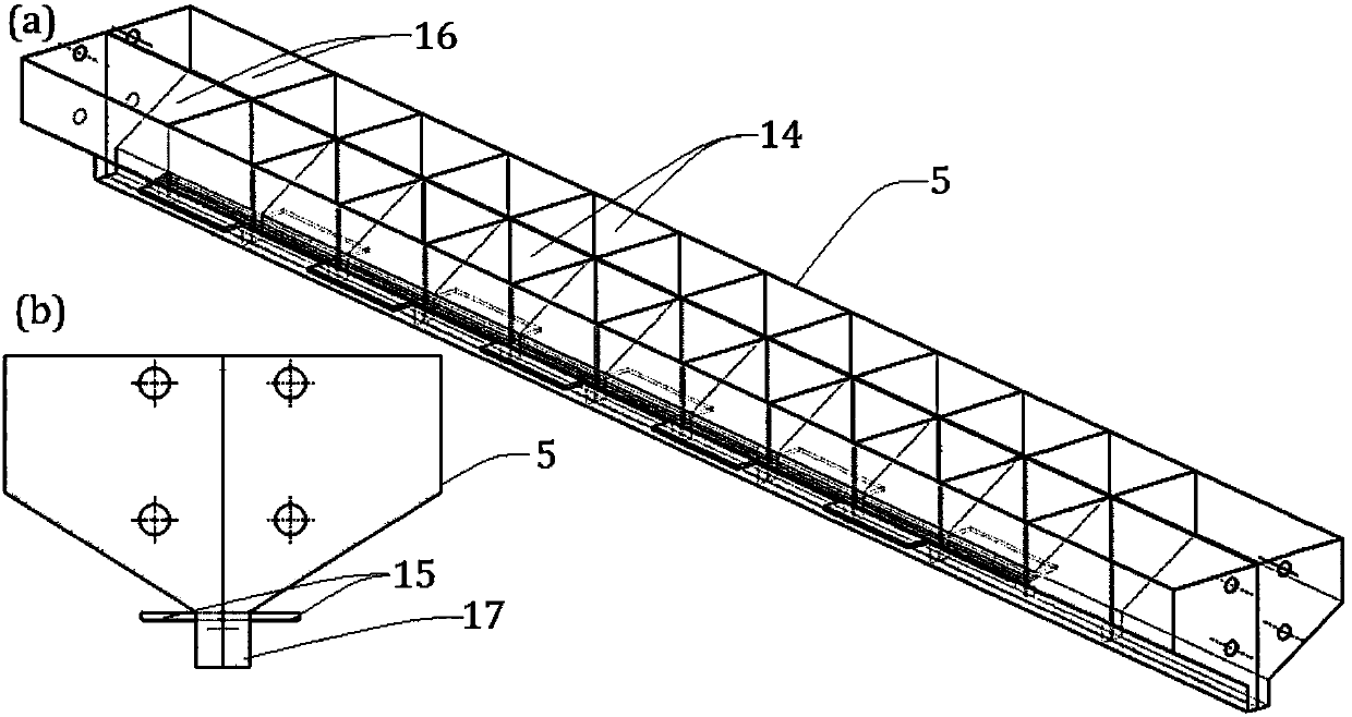
[0048] The difference from Example 1 is that, as Figure 4 As shown, the selective paving mechanism 5 is provided with a follow-up nozzle switch 15, and the follow-up nozzle switch 15 can move back and forth in the longitudinal direction as a whole; while performing horizontal scanning and laying, it can dynamically control the forming according to the forming requirements. Material and auxiliary molding material blanking range; if the follow-up nozzle switch 15 is closed, the auxiliary molding material will drop, otherwise the molding material will drop.


PUM


Abstract

The invention provides a sand mold printing device and method and belongs to the technical field of 3D printing. The sand mold printing device comprises a base, a forming box trolley, a blanking bracket, a selective laying mechanism, a blanking mechanism, a forming material feeding hopper, an auxiliary forming material feeding hopper, a forming material conveying mechanism, an auxiliary forming material conveying mechanism and a control unit; wherein the base is provided with a guide rail; a printing platform is movably arranged in the forming box trolley which is movably connected with the guide rail; the blanking bracket is erected above the guide rail and fixedly connected with the base; the selective laying mechanism and the blanking mechanism are sequentially fixed to the blanking bracket from bottom to up; the forming material feeding hopper and the auxiliary forming material feeding hopper are arranged on the blanking mechanism in an alternated mode; and the forming material conveying mechanism and the auxiliary forming material conveying mechanism are connected with the forming material feeding hopper and the auxiliary forming material feeding hopper correspondingly. According to the sand mold printing device and method, a linear forming mode is adopted, forming materials and auxiliary forming materials are selectively laid, 3D printing of a sand mold is achieved, and thus the forming speed can be increased.

Description

technical field [0001] The present invention relates to a technique in the field of 3D printers, in particular to a sand casting mold printing device without inversion and a printing method thereof. Background technique [0002] At present, domestic sand mold printing equipment for foundry is limited to filling with a single nozzle according to the trajectory or laying sand and binder layer by layer in combination with CNC technology, and then cutting according to demand, the molding speed is slow and the efficiency is low; while foreign equipment uses multi-nozzle arrays one by one Layers of auxiliary raw sand and curing agent are laid in sequence, and the nozzle moves along the two-dimensional plane. The existing technologies are point scanning or dot matrix scanning molding, and the speed is relatively slow, especially for printing sand molds for large castings. [0003] After searching the prior art, it was found that Chinese Patent Document No. CN105235221A, published ...

Claims


Application Information

Patent Timeline
Patent Type & Authority Patents(China)
IPC IPC(8): B29C67/00B28B1/00B22C9/02B33Y10/00B33Y30/00B33Y50/02
CPCB22C9/02B28B1/001B33Y10/00B33Y30/00B33Y50/02
Inventor 郭为忠张白冰赵冬华高峰
Owner SHANGHAI JIAO TONG UNIV
Why Eureka
Try Eureka