Light gantry structure for large 3D printer

A 3D printer and gantry technology, applied in the direction of additive processing, etc., can solve the problems of non-parallel two Z axes, inaccurate running accuracy, and insufficient gantry movement, etc., to achieve simplified mechanism, high printing accuracy, and light movement speed Effect

Active Publication Date: 2016-08-10
WUHU AISANDI ELECTRONICS TECH CO LTD
View PDF6 Cites 16 Cited by
  • Summary
  • Abstract
  • Description
  • Claims
  • Application Information

AI Technical Summary

Problems solved by technology

[0003] FDM-based 3D printers in the prior art will encounter deficiencies when they are used too often. For example, most of the existing large-scale 3D printers have a gantry structure, and most gantry structures use a double-Z structure. There is a defect in the double-Z structure. That is, the two Z axes are not parallel, so that the printed workpiece will have a defect that one end is high and the other end is low; another problem is that the structure of the gantry type is mostly too complicated, the structure is too heavy, and it is cumbersome during operation, resulting in the entire gantry. It is not fast enough when moving, and there will be shaking, especially when there is an emergency stop, there is an inertia to rush forward suddenly, which leads to inaccurate running accuracy, and the printed model is naturally inaccurate

Method used


Image

  • Light gantry structure for large 3D printer
  • Light gantry structure for large 3D printer
  • Light gantry structure for large 3D printer

Examples


Embodiment Construction

[0024] The present invention will be further described in conjunction with the accompanying drawings and specific embodiments. It should be understood that these examples are only used to illustrate the present invention and are not intended to limit the scope of the present invention. In addition, it should be understood that after reading the teachings of the present invention, those skilled in the art can make various changes or modifications to the present invention, and these equivalent forms also fall within the scope defined by the appended claims of the present application.

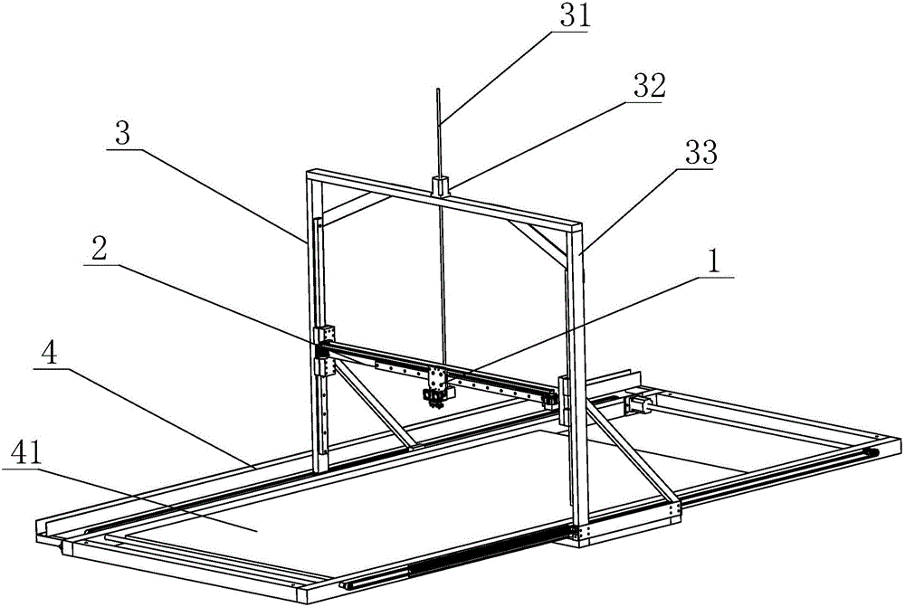
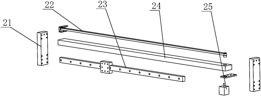
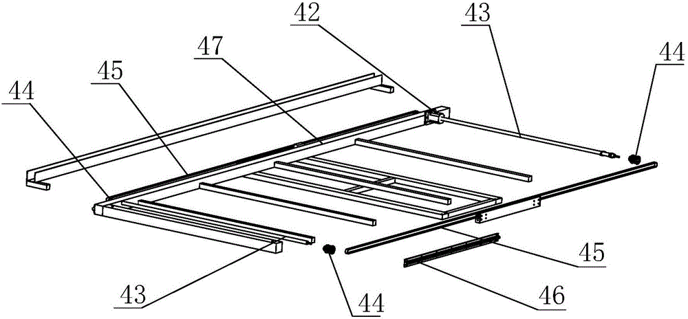
[0025] as attached figure 1 As shown, a light gantry large-scale 3D printer structure includes an X-axis module 2, a Y-axis module 4 and a Z-axis module 3, and the Z-axis module 3 includes a gantry frame 33 and a Z-axis lifting mechanism, The Z-axis lifting mechanism includes a Z-axis motor 32 and a screw 31 installed at the center of the gantry frame 33, the X-axis module 2 is installed on the g...


PUM


Abstract

The invention provides a light gantry structure for a large 3D printer. The light gantry structure for the large 3D printer comprises an X-axis module, a Y-axis module and a Z-axis module. The Z-axis module comprises a gantry type frame and a Z-axis lifting mechanism. The Z-axis lifting mechanism comprises a Z-axis motor and a lead screw, wherein the Z-axis motor and the lead screw are mounted in the center position of the gantry type frame. The X-axis module is mounted on the gantry type frame of the Z-axis module. The lead screw is connected to the middle of the X-axis module to drive the X-axis module to ascend or descend on the gantry type frame. An extrusion machine capable of moving along the X axis is mounted on the X-axis module. The Y-axis module is arranged at the bottom of the gantry type frame. A working platform is arranged on the Y-axis module. The gantry type frame is in sliding fit with the Y-axis module. The 3D printer acts on the middle of the X-axis module through the single lead screw in the Z-axis direction, the mechanism is simplified, the stress of the lead screw is uniform, and meanwhile the gantry type printer structure is simple, stable to operate and capable of guaranteeing precise printing of a model.

Description

technical field [0001] The invention mainly relates to the technical field of 3D printers, in particular to a large-scale 3D printer structure with light gantry. Background technique [0002] 3D printer is a machine of rapid prototyping technology, which is based on a digital model file, using bondable materials such as powdered metal or plastic, to construct objects by layer-by-layer printing. The three-dimensional printer of the prior art It is mainly divided into fused deposition modeling (FDM), selective laser sintering (SLS), stereolithography (SLA) and digital light processing (DLP). [0003] FDM-based 3D printers in the prior art will encounter deficiencies when they are used too often. For example, most of the existing large-scale 3D printers have a gantry structure, and most gantry structures use a double-Z structure. There is a defect in the double-Z structure. That is, the two Z axes are not parallel, so that the printed workpiece will have the defect that one en...

Claims


Application Information

Patent Timeline
Patent Type & Authority Applications(China)
IPC IPC(8): B29C67/00B22F3/115B33Y30/00
CPCB22F3/115B33Y30/00
Inventor 张文义
Owner WUHU AISANDI ELECTRONICS TECH CO LTD
Why Eureka
Try Eureka