
Automatic material taking device and material taking method for J53-300T friction press

A friction press, automatic reclaiming technology, applied in packaging, conveyors, conveyor objects, etc., can solve the problems of poor working environment, unfavorable health of workers, and high labor intensity of workers, so as to improve the working environment and save money. Manual, solve the effect of high labor intensity

Active Publication Date: 2016-08-10
CHINA RAILWAY LONGCHANG MATERIALS
View PDF6 Cites 1 Cited by
  • Summary
  • Abstract
  • Description
  • Claims
  • Application Information

AI Technical Summary

Problems solved by technology

[0002] The general J53-300T friction press adopts the manual method of retrieving materials. Workers take out the produced workpieces one by one from the J53-300T friction press. During production, they must not leave people. Some people have been squatting there to pick up materials. The labor intensity of the workers is high, the production efficiency is low and the degree of automation is not high; sometimes there are even cases where the workpiece is crushed due to human-made failure to pick up the materials in time, which ultimately affects product quality.
At the same time, the workers are too close to the J53-300T friction press. Because the workpiece is thermoformed, a large amount of smoke and high temperature are generated during heating. The working environment of the workers is harsh, especially in summer when the temperature is very high. Long-term exposure to high temperature environment is not good for workers' health

Method used


Image

  • Automatic material taking device and material taking method for J53-300T friction press
  • Automatic material taking device and material taking method for J53-300T friction press
  • Automatic material taking device and material taking method for J53-300T friction press

Examples


Embodiment Construction

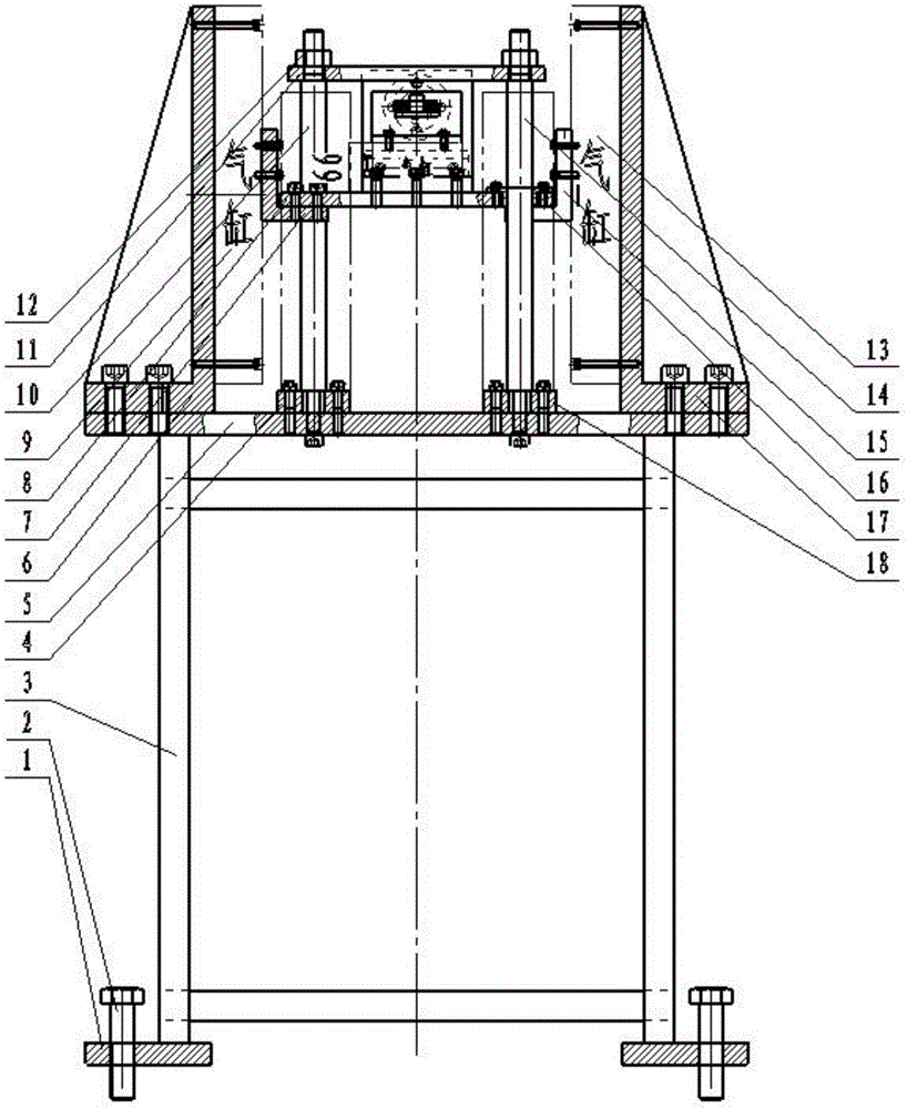
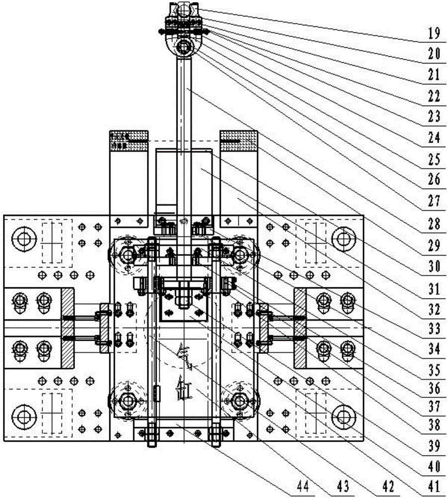
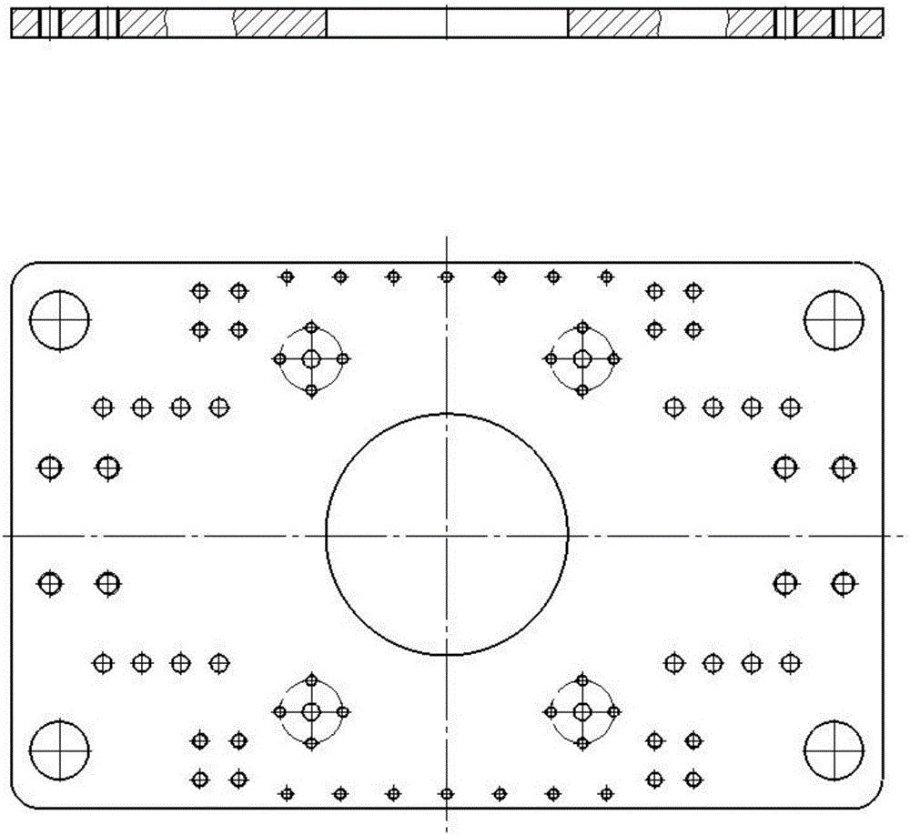
[0025] A J53-300T friction press automatic feeding device, such as figure 1 and figure 2 As shown, it includes: height adjustment plate 1, height adjustment bolt 2, bracket 3, first base 4, bottom plate 5, left cylinder support 6, left L-shaped connecting plate 7, movable plate 8, left cylinder 9, first guide Rod 10, fixed plate 11, hex nut 12, right cylinder 13, second guide rod 14, right L-shaped connecting plate 15, first copper sleeve 16, right cylinder support 17, second base 18, right jaw 19, Left jaw 20, middle jaw 21, right turning piece 22, double-ended stud 23, cylindrical helical compression spring 24, left turning piece 25, second copper sleeve 26, threading pin 27, telescopic rod 28, safety grating sensor 29 , limit plate 30, first adjustment plate 31, second adjustment plate 32, guide seat 33, third copper sleeve 34, front support 35, fourth copper sleeve 36, guide plate 37, fifth copper sleeve 38, hexagonal Nut 39, push plate 40, third guide rod 41, fourth gu...


PUM


Abstract

The invention discloses an automatic material taking device and material taking method for a J53-300T friction press. The automatic material taking device comprises an up-down vertical moving part and a front-back horizontal moving part; through the action of a telescopic cylinder, a telescopic rod is driven to extend forwards, and then a material is clamped by a material clamping device; through the simultaneous action of a left cylinder and a right cylinder, a movable plate is driven to rise, and then the material is separated from a mold; through reset of the telescopic cylinder, the telescopic rod is horizontally retracted backwards, and then the material is pushed by a limiting plate from the material clamping device to fall in a hopper; and finally, the left cylinder and the right cylinder simultaneously act to reset, so that the movable plate is driven to fall to the initial position. By adoption of the automatic material taking device provided by the invention, the friction press achieves automatic material taking, the control is precise, and the applicability is high; manual material taking operation is replaced by mechanical material taking operation, so that the labor is saved, the cost is reduced, and the labor environment of workers is improved; and meanwhile, assembly line operation can be achieved, thereby achieving the purpose of improving the production efficiency and the degree of automation.

Description

technical field [0001] The invention relates to an automatic material retrieving device and method for a J53-300T friction press. Background technique [0002] The general J53-300T friction press adopts the manual method of retrieving materials. Workers take out the produced workpieces one by one from the J53-300T friction press. During production, they must not leave people. Some people have been squatting there to pick up materials. The labor intensity of the workers is high, the production efficiency is low, and the degree of automation is not high. Sometimes there are even cases where the workpiece is crushed due to human-made failure to pick up the materials in time, which ultimately affects the product quality. At the same time, the workers are too close to the J53-300T friction press. Because the workpiece is thermoformed, a large amount of smoke and high temperature are generated during heating. The working environment of the workers is harsh, especially in summer wh...

Claims


Application Information

Patent Timeline
Patent Type & Authority Applications(China)
IPC IPC(8): B65G47/90B65G47/82
CPCB65G47/82B65G47/901B65G47/905B65G2203/044B65G2207/40
Inventor 杨安波
Owner CHINA RAILWAY LONGCHANG MATERIALS
Learn More