

Flush toilet
A toilet, flushing technology, applied in flushing toilets, water supply devices, sanitary equipment for toilets, etc. Effect of dirt discharge performance
- Summary
- Abstract
- Description
- Claims
- Application Information
AI Technical Summary
Problems solved by technology
Method used
Image

Examples
Embodiment Construction
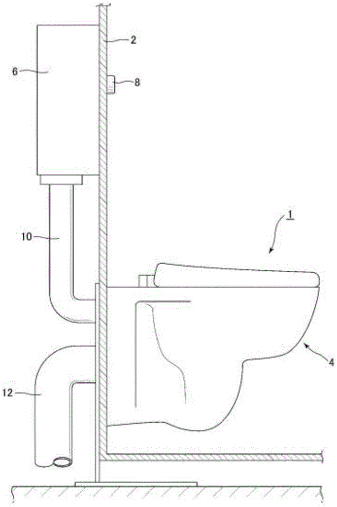
[0032] Next, a flush toilet according to an embodiment of the present invention will be described with reference to the drawings. figure 1 It is an overall schematic diagram showing the flush toilet according to the embodiment of the present invention.
[0033] The flush toilet according to the embodiment of the present invention is a flush-type flush toilet (flush-type flush toilet) that flushes away waste by utilizing the action of flowing water caused by the head of water in the bowl. In addition, this embodiment can also be applied to the siphon type flush toilet other than the flush type flush toilet, etc.
[0034] like figure 1 As shown, the flush toilet 1 according to the embodiment of the present invention includes a toilet body 4 mounted on the front surface of the wall 2 , and a water storage tank 6 for storing cleansing water as a cleansing water source installed on the back surface above the wall 2 . In addition, an operation switch 8 is attached to the surface o...
PUM
 Abstract
Description
Claims
Application Information