
Vehicle starter control method and vehicle

A control method and starter technology, applied to engine components, engine starting, machine/engine, etc., can solve starter misstart, increase microcontroller, interface circuit manufacturing, installation and maintenance costs, running time burnout and other problems, to achieve the effect of improving safety performance, avoiding false start of the starter, and controlling high efficiency

Active Publication Date: 2016-08-10
SAIC GENERAL MOTORS +1
View PDF9 Cites 4 Cited by
  • Summary
  • Abstract
  • Description
  • Claims
  • Application Information

AI Technical Summary

Problems solved by technology

However, directly determining whether the starter is working by the working state of the ignition switch, there is a risk that the starter will be dragged backwards once the engine speed is too high, causing the latter to run for too long and be burned out, and there is also the possibility Risk of false starting of the starter due to a faulty ignition switch signal line
[0003] In view of the above problems, the currently adopted solutions can be divided into two types: one is to increase the protection circuit to limit the working time of the starter, such as the Chinese patent application with the application number 201220728583.6, but the circuit cost needs to be increased in this way , and is limited in principle to cut off the starter current by limiting the on-time, and cannot accurately judge the starting state of the vehicle; another solution is to add a microcontroller as a starter protection module, In order to independently control the on-off state of the starter, for example, the Chinese patent applications with application numbers 201220280870.5 and 201010535798.1, although these technical solutions can better judge the working conditions of the starter and cut off the current in time, the disadvantages are also obvious For example, it increases the manufacturing, installation and maintenance costs of devices such as microcontrollers and interface circuits, and inevitably increases the complexity of the vehicle's electronic system

Method used


Image

  • Vehicle starter control method and vehicle
  • Vehicle starter control method and vehicle
  • Vehicle starter control method and vehicle

Examples


Embodiment Construction

[0027] First of all, it should be noted that the vehicle starter control method of the present invention and the specific control steps, features and advantages of the vehicle will be described in detail below by way of example. However, all descriptions are only for illustration and should not be used. It is to be construed as forming any limitation on the invention. In addition, any single technical feature described or implied in each embodiment mentioned herein, or any single technical feature shown or implied in each drawing, can still be described in these technical features (or their equivalents) ) to continue any combination or deletion, so as to obtain more other embodiments of the present invention that may not be directly mentioned herein. In addition, for the sake of simplifying the drawings, the same or similar parts and features may only be marked at one or several places in the same drawing.

[0028] Please refer to figure 1 , where the figure shows the releva...


PUM


Abstract

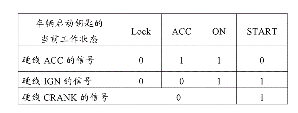
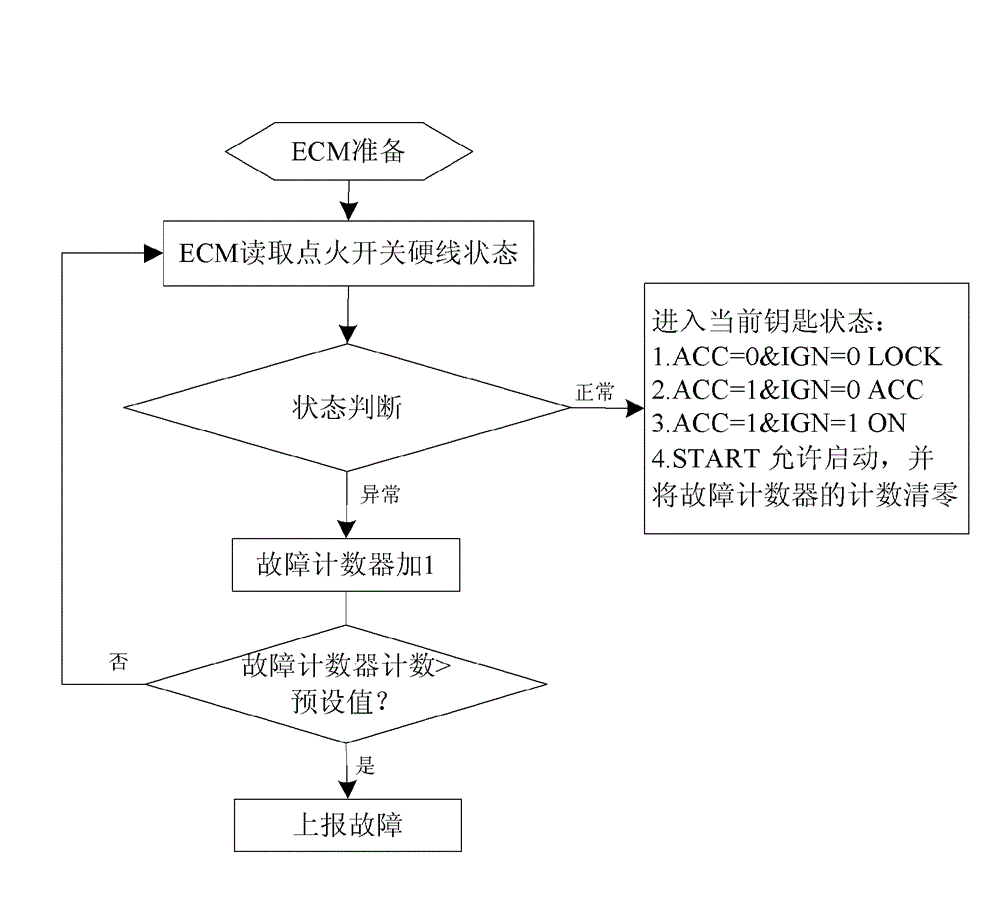
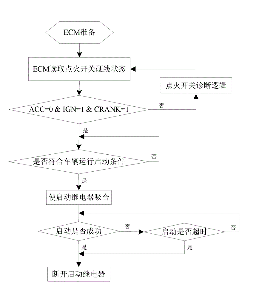
The invention relates to a vehicle starter control method and a vehicle. The vehicle starter control method comprises: joining the rigid lines ACC, IGN, and CRANK of an ignition switch with a starter control module ECM, the starter control module ECM determining the current working state of a vehicle start key according to the signals of the rigid lines ACC and IGN, and according to the signals of the rigid line CRANK, verifying the determined current working state, to determine whether the ignition switch satisfies a start state; when the starter control module ECM determines the ignition switch satisfies the start state and a vehicle operation start condition is met, the starter control module ECM sending out an instruction to make a starting relay pick up to drive a starter to operate; when the starter control module ECM determines the starter is successfully started or the starting time of the starter exceeds a preset value, the starter control module ECM sending out an instruction to cut off the starting relay to cut off current of the starter. The method is advantaged by safe and reliable, and high-efficiency control, easy realization, and low cost.

Description

technical field [0001] The invention relates to the technical field of vehicle start control, in particular to a vehicle starter control method and a vehicle using the vehicle starter control method. Background technique [0002] In the prior art, when the starter motor on the vehicle is working, a large current such as 300-400A is generally passed through, so it is very easy to cause these starter motors to be burned out after a long time of starting. For this reason, for example, for a vehicle model that is not equipped with a body control module, the traditional method is to directly control the relay by the ignition switch, thereby controlling the work of the starter. However, directly determining whether the starter is working by the working state of the ignition switch, there is a risk that the starter will be dragged backwards once the engine speed is too high, causing the latter to run for too long and be burned out, and there is also the possibility Risk of false s...

Claims


Application Information

Patent Timeline
IPC IPC(8): F02N11/08
Inventor 沈成宇傅忠华李竟成吴斌
Owner SAIC GENERAL MOTORS
Learn More