Optical fiber merging jig

A fixture and optical fiber technology, applied in the direction of bundled optical fibers, etc., can solve the problems of non-standard bending and easy breaking of optical fibers, and achieve the effect of convenient operation and simple structure.

Inactive Publication Date: 2016-08-10
SUZHOU WEIMI OPTICS TECH CO LTD
View PDF6 Cites 0 Cited by
  • Summary
  • Abstract
  • Description
  • Claims
  • Application Information

AI Technical Summary

Problems solved by technology

Fibers are bundled manually, which makes the ...

Method used


Image

  • Optical fiber merging jig

Examples


Embodiment Construction

[0012] Specific embodiments of the present invention will be further described in detail below.

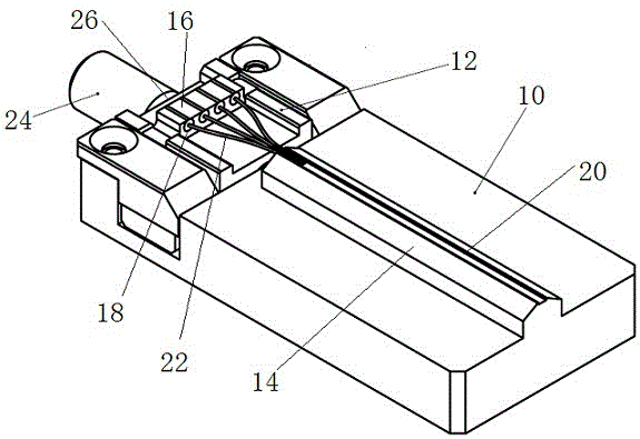
[0013] Such as figure 1 As shown, an optical fiber bundling jig of the present invention includes a base 10 on which a positioning plate 12 and a bundling base 14 are arranged. The positioning plate 12 and the belt base 14 can be integrally formed with the base 10 , or can be fixed on the base 10 by means of screw fixing or the like. In this embodiment, a screw fixing method is adopted, which is convenient for processing, disassembly and replacement, and thus is applicable to the occasion where multiple optical fiber products of different specifications are paralleled. A pressing plate 16 is detachably clamped in the positioning plate 12, and a plurality of positioning holes 18 parallel to each other are arranged on the pressing plate 16, and a groove 20 is arranged on the belt base 14, and the groove 20 is parallel to the positioning holes 18. In this way, several optical fiber...


PUM


Abstract

The invention discloses an optical fiber tie-in jig, which includes a base, and is characterized in that: the base is provided with a pressing plate and a tie-in base, and the pressing plate is provided with several positioning holes parallel to each other. And a groove is arranged on the belt base, and the groove is parallel to the positioning hole. The optical fiber bundling jig of the present invention limits the position of the optical fiber through a simple structure, and assists the operation of the optical fiber bundling. The jig for combining optical fibers of the invention has the advantages of simple structure, convenient operation and the like.

Description

technical field [0001] The invention relates to an optical fiber and tape jig. Background technique [0002] Optical fiber bundling is to combine multiple parallel optical fibers into one strand after bending. Its function is to set the connector at the fiber head, and the combined part is protected by the sleeve. Fibers are bundled manually, which makes the bending of the fibers non-standard and easy to break. How to combine optical fibers in a standard and convenient way is the technical problem to be solved by the present invention. Contents of the invention [0003] In order to overcome the above-mentioned problems, the present invention provides a safe and reliable fiber optic fixture with simple structure and simple operation. [0004] The technical solution of the present invention is to provide an optical fiber and belt fixture, which includes a base, and is characterized in that: a pressing plate and a belt base are arranged on the base, and several positioning...

Claims


Application Information

Patent Timeline
IPC IPC(8): G02B6/04
CPCG02B6/04
Inventor 陈洪良
Owner SUZHOU WEIMI OPTICS TECH CO LTD
Why Eureka
Try Eureka