Method for Post Optical Proximity Correction Restoration

A technology of optical proximity correction and photomask, which is applied in the field of semiconductors and can solve problems such as increased technical difficulty

Active Publication Date: 2020-03-10
SEMICON MFG INT (SHANGHAI) CORP
View PDF5 Cites 0 Cited by
  • Summary
  • Abstract
  • Description
  • Claims
  • Application Information

AI Technical Summary

Problems solved by technology

However, ignoring the MRC rules will lead to increased technical difficulties in preparing the desired reticle

Method used


Image

  • Method for Post Optical Proximity Correction Restoration
  • Method for Post Optical Proximity Correction Restoration
  • Method for Post Optical Proximity Correction Restoration

Examples


Embodiment Construction

[0021] In the following description, numerous specific details are given in order to provide a more thorough understanding of the present invention. It will be apparent, however, to one skilled in the art that the present invention may be practiced without one or more of these details. In other examples, some technical features known in the art are not described in order to avoid confusion with the present invention.

[0022] It should be understood that the invention can be embodied in different forms and should not be construed as limited to the embodiments set forth herein. Rather, these embodiments are provided so that this disclosure will be thorough and complete, and will fully convey the scope of the invention to those skilled in the art.

[0023] The terminology used herein is for the purpose of describing particular embodiments only and is not intended to be limiting of the invention. As used herein, the singular forms "a", "an" and "the / the" are intended to include...


PUM


Abstract

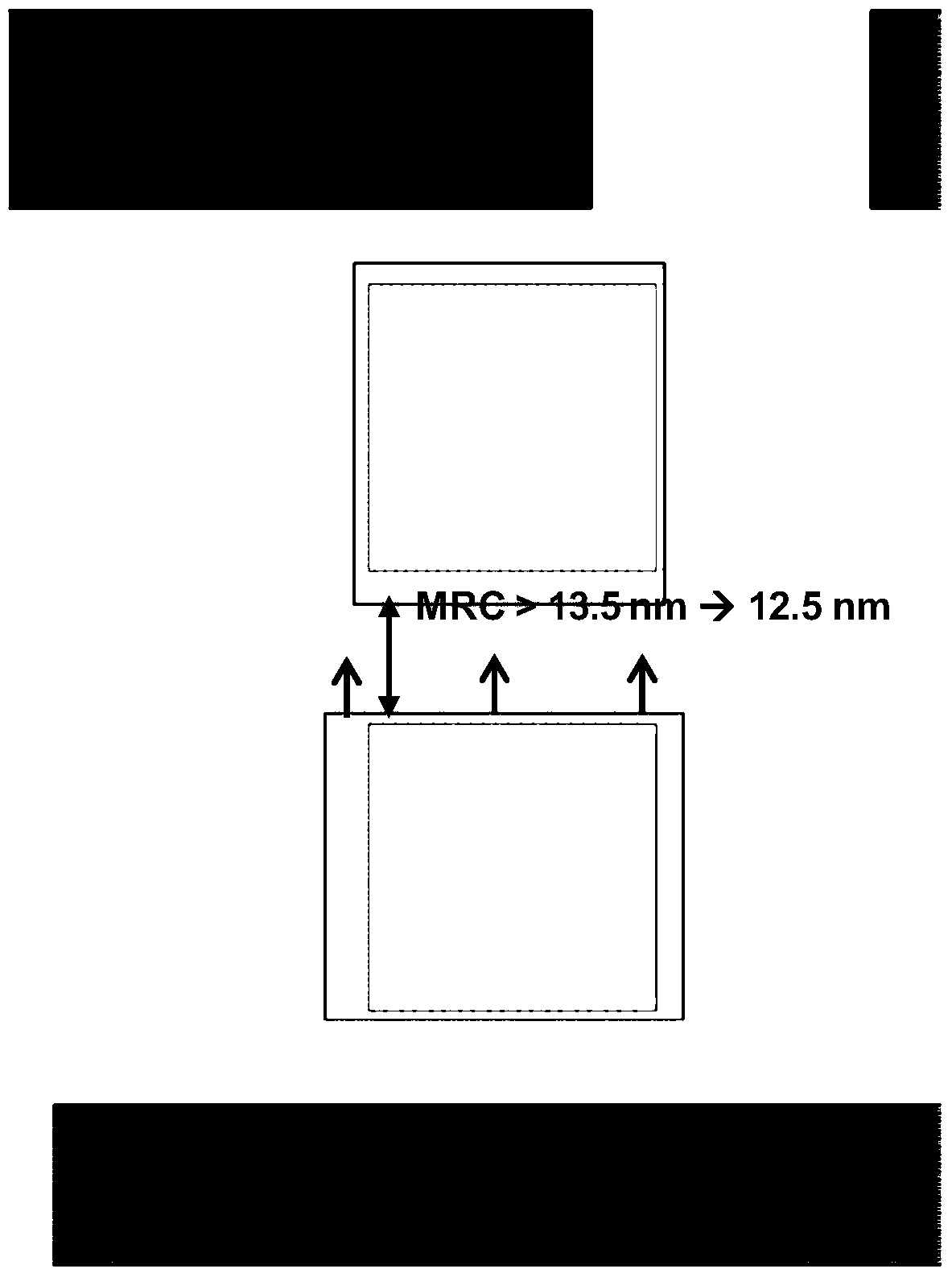
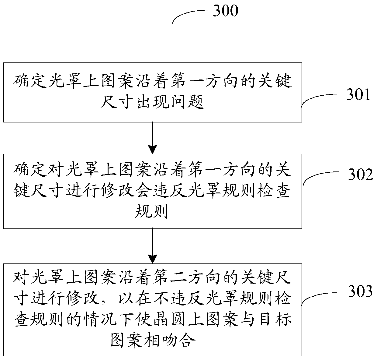
The invention provides a method for post-optical proximity correction repair. The method comprises: determining that a pattern on a photomask along a critical size of a first direction goes wrong; determining that modification of the pattern on the photomask along the critical size of the first direction can break a photomask checking rule; and modifying the pattern on the photomask along the critical size of a second direction so as to inosculate a pattern on a wafer with a target pattern without breaking the photomask checking rule. The method for post-optical proximity correction repair provided by the invention does not directly repair the part of pattern going wrong on the photomask, but repairs another part of the pattern on the photomask, thus indirectly realizing anastomosis of the pattern on the wafer and the target pattern under the circumstance of avoiding breaking the photomask checking rule caused by direct modification of the problem part.

Description

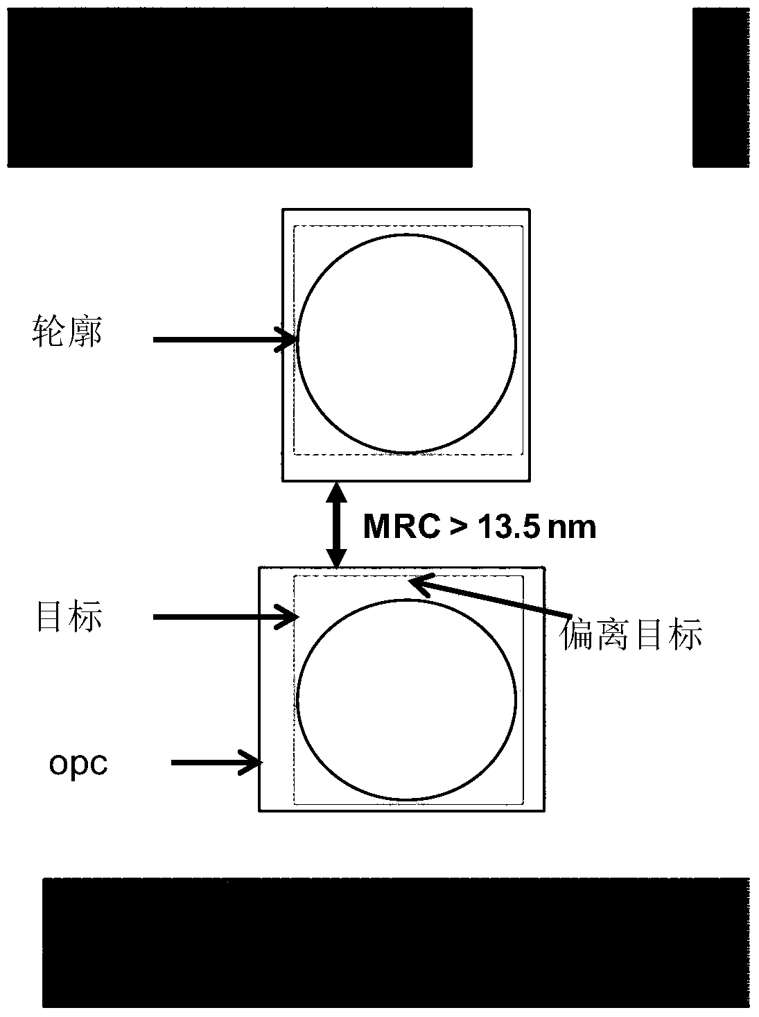
technical field [0001] The present invention relates to the technical field of semiconductors, in particular to a method for post Optical Proximity Correction repair (post-OPC repair). Background technique [0002] As the complexity of integrated circuits increases, the feature size becomes smaller and smaller. When the feature size of the integrated circuit is close to the system limit of the exposure of the lithography machine, that is, when the feature size is close to or smaller than the lithography light source, the layout produced on the silicon wafer will be obviously distorted. This phenomenon is called the optical proximity effect. In order to deal with the optical proximity effect, a resolution enhancement technique is proposed. Among them, Optical Proximity Correction (OPC) has become the most important technology. [0003] OPC is not a process in which accurate results can be obtained once, it is an iterative process that requires multiple verifications and mod...

Claims


Application Information

Patent Timeline
Patent Type & Authority Patents(China)
IPC IPC(8): G03F1/36
Inventor 杜杳隽杨青
Owner SEMICON MFG INT (SHANGHAI) CORP
Why Eureka
Try Eureka