Random particle-based dynamic vortex flow field visualization method

A particle and flow field technology, applied in the field of marine data visualization, can solve problems such as movement changes in difficult flow fields, and achieve good visual effects

Active Publication Date: 2016-08-10
INST OF GEOGRAPHICAL SCI & NATURAL RESOURCE RES CAS
View PDF3 Cites 4 Cited by
  • Summary
  • Abstract
  • Description
  • Claims
  • Application Information

AI Technical Summary

Problems solved by technology

[0004] These existing methods, ranging from simple to complex, express the flow field vector data from different degrees of vividness, but it is difficult for use

Method used


Image

  • Random particle-based dynamic vortex flow field visualization method
  • Random particle-based dynamic vortex flow field visualization method

Examples


Embodiment Construction

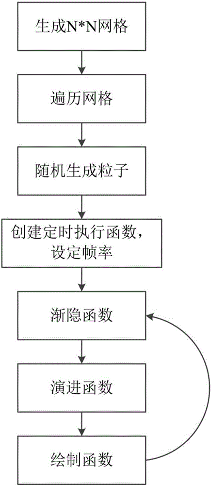
[0035] Such as figure 1 Shown, the specific implementation steps of the present invention are as follows:

[0036] Step 1. Generate N*N regular grids in space according to actual user needs, and traverse each grid.

[0037] Step 2. Randomly generate a particle in the grid, and give the particle a specified or random lifespan value. The calculation is as follows,

[0038] x=x 0 +size*random();

[0039] y=y 0 +size*random();

[0040] age=max_age*random();

[0041] Among them, (x, y) is the random position generated by the particle, (x 0 ,y 0 ) is the starting point of the grid, size is the length of the grid, age is the random life value of the particle, max_age is the maximum life value of the particle set by the user, random() is the method that generates any value in the interval [0,1] random function.

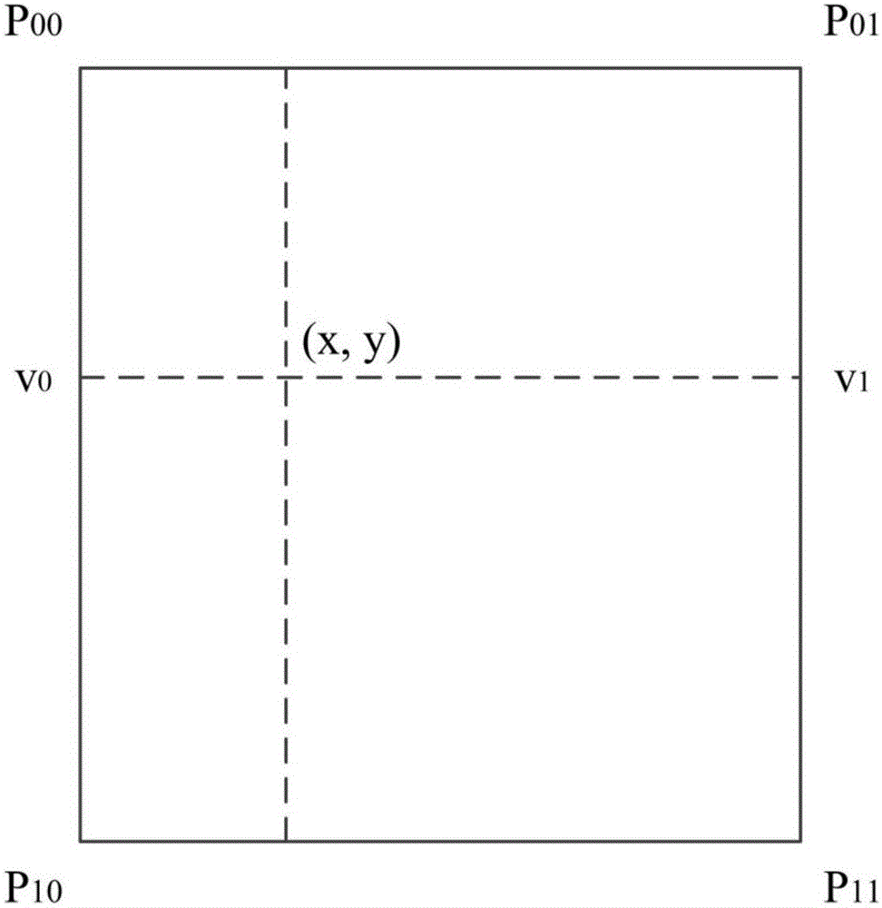
[0042] Step 3. According to the spatial position (x, y) of the particle, search for the four nearest sampling points P in the flow field vector data 00 ,P 01 ,P 1...


PUM


Abstract

The invention discloses a random particle-based dynamic vortex flow field visualization method. Through the method, particles are randomly generated in a flow field and are endowed with life lengths, so that the particles constantly move along with the change of velocity vectors of the flow field, so as to form a movement track which is used for presenting the flow line characteristics of the vortex closed flow field. The method disclosed in the invention is simple in algorithm, high in calculation speed, vivid in visual effect and suitable for the dynamic visualization of other flow field phenomena such as vortex and the like.

Description

technical field [0001] The invention relates to a dynamic visualization method of a vortex flow field based on random particles, belonging to the field of ocean data visualization. Background technique [0002] The current field is an important physical field in ocean research, such as the wind in the atmosphere and the current in the ocean are important driving forces for many ocean dynamic phenomena (eddies, tides, waves, fronts, etc.). Flow field data usually adopts the data structure of vector field, which records the velocity in the horizontal U (latitudinal) and vertical V (longitudinal) directions at each sampling point. Since the flow field data itself cannot intuitively reflect the magnitude and direction of the velocity at each position of the flow field, how to effectively and vividly visualize the flow field data and express the closed circulation characteristics of the mesoscale vortex on the flow field is very important for understanding and It is of great sig...

Claims


Application Information

Patent Timeline
IPC IPC(8): G06F17/50
CPCG06F30/18
Inventor 易嘉伟杜云艳周成虎
Owner INST OF GEOGRAPHICAL SCI & NATURAL RESOURCE RES CAS
Why Eureka
Try Eureka