Large power loaded MOS pipe heat radiation apparatus

A high-power load, MOS tube technology, applied in electrical components, electrical solid devices, circuits, etc., can solve the problems of large heat generation, low effective utilization of radiators, large wind resistance, etc., to achieve comprehensive personal safety protection, radiator The effect of high utilization rate and high working voltage

Active Publication Date: 2016-08-10
武汉精能电子技术有限公司 +1
View PDF7 Cites 1 Cited by
  • Summary
  • Abstract
  • Description
  • Claims
  • Application Information

AI Technical Summary

Problems solved by technology

[0002] There are many MOS tubes in high-power loads, and the heat generated during work is large. If the heat cannot be dissipated in time, the temperature of the MOS tubes will be very high. Eventually, the MOS tubes will burn out due to the high temperature, resulting in the failure of the entire load to work normally.
[0003] Traditional high-power load MOS tube cooling devices such as figure 1 as shown, figure 2 Yes figure 1 In the illustration of moving the fan back to the radiator, the high-power MOS tube is set on the circuit board, the circuit board is placed on the radiator, and the MOS tube is in contact with the surface of the radiator substrate. When the circuit is working, the heat emitted by the MOS tube The radiator is quickly dissipated by the fan. If the power of the circuit is large, the number of MOS tubes will be more. According to the current heat dissipation structure of the MOS tube, only the length of the radiator and the circuit board can be increased to dissipate heat for the MOS tube. , doing so will increase the depth of the chassis, and at the same time, the effective utilization rate of the heat sink of this heat dissipation structure is low, and the wind resistance is large, resulting in poor heat dissipation, and at the same time, the noise is large, and the fan will resonate with the heat sink when it is working, which may cause The looseness of the screw on the MOS tube leads to the inability of the MOS tube to be tightly attached to the radiator substrate, the heat of the MOS tube cannot be transferred to the radiator, and the MOS tube eventually burns out.

Method used


Image

  • Large power loaded MOS pipe heat radiation apparatus
  • Large power loaded MOS pipe heat radiation apparatus
  • Large power loaded MOS pipe heat radiation apparatus

Examples


Embodiment

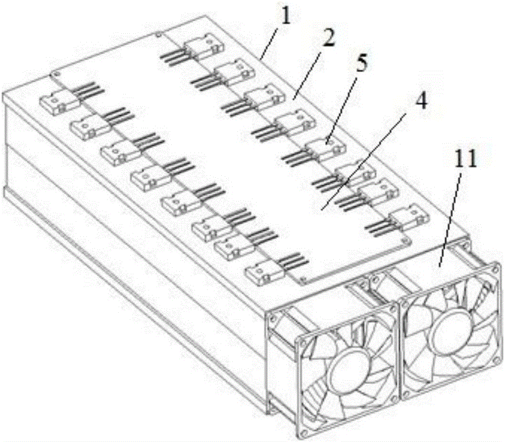
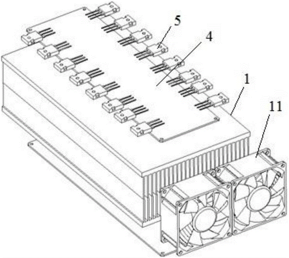
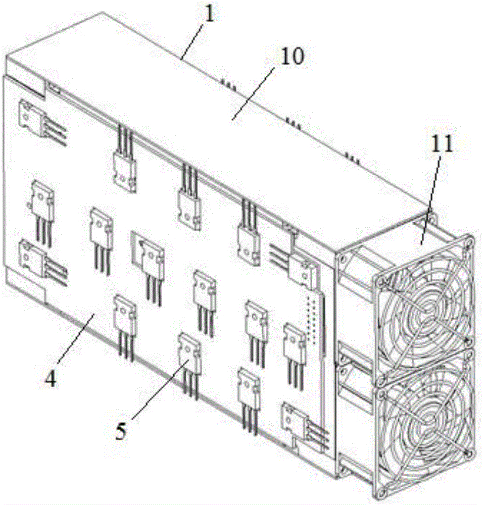
[0024] Such as image 3 , Figure 4 As shown, the high-power load MOS tube cooling device in this embodiment includes a radiator 1, a fan 11 is installed at the inlet end of the radiator 1, and a circuit board 4 is respectively fixed on the substrate 2 on both sides of the radiator 1. A plurality of MOS tubes 5 are installed on the circuit board 4, the body 5.1 of the MOS tube 5 is close to the surface of the substrate 2, and a fireproof insulation board 7 is arranged between the circuit board 4 and the surface of the substrate 2 of the radiator 1, and the radiator 1 An anti-vibration pad 12 is arranged between the fan 11.

[0025] In this embodiment, circuit boards 4 are arranged on both sides of the radiator 1, and MOS tubes 5 are installed on each circuit board 4, so that more MOS tubes can be installed without increasing the size of the radiator, and the utilization rate of the radiator is improved. high.

[0026] The fireproof insulating board 7 of the present embodime...


PUM


Abstract

The invention discloses a large power loaded MOS pipe heat radiation apparatus. The apparatus comprises a heat radiator. The inlet end of the radiator is provided with a fan. The substrates at both sides of the radiator are fixedly provided with circuit boards respectively. The circuit boards are provided with a plurality of MOS pipes. The MOS pipe bodies are in close contact with the surfaces of the substrates, and fireproof insulated panels are mounted between the circuit boards on one hand and the substrate surfaces of the radiator on the other hand. A crash pad is arranged between the radiator and the fan. The apparatus, with good heat radiation performance and little noise, can provide comprehensive protection to a person and can tolerate higher working voltage in limited space.

Description

technical field [0001] The invention belongs to the technical field of electronic circuits, and in particular relates to a high-power load MOS tube cooling device. Background technique [0002] High-power loads have a large number of MOS tubes and generate a lot of heat during operation. If the heat cannot be dissipated in time, the temperature of the MOS tubes will be very high. Eventually, the MOS tubes will burn out due to the high temperature, resulting in the failure of the entire load to work normally. [0003] Traditional high-power load MOS tube cooling devices such as figure 1 as shown, figure 2 yes figure 1 In the illustration of moving the fan back to the radiator, the high-power MOS tube is set on the circuit board, the circuit board is placed on the radiator, and the MOS tube is in contact with the surface of the radiator substrate. When the circuit is working, the heat emitted by the MOS tube The radiator is quickly dissipated by the fan. If the power of th...

Claims


Application Information

Patent Timeline
IPC IPC(8): H01L23/367H01L23/467
CPCH01L23/3675H01L23/467H01L2023/4087
Inventor 武猛
Owner 武汉精能电子技术有限公司
Why Eureka
Try Eureka