
Equipment clamp punching positioning device

A technology for equipment wire clips and hole positioning, which is applied in the manufacturing of contacts, etc., can solve the problems of inaccurate punching, trouble in determining the position of the drip hole punching, discharge, etc., to improve work efficiency, simple and reliable measurement, and ensure normal operation. Effect

Inactive Publication Date: 2016-08-10
国网山东省电力公司乳山市供电公司
View PDF0 Cites 1 Cited by
  • Summary
  • Abstract
  • Description
  • Claims
  • Application Information

AI Technical Summary

Problems solved by technology

If the position of the drip hole is not suitable, the accumulated water cannot be removed in time, it is easy to cause freezing and cracking in winter, and it can also cause discharge, the gap becomes larger, and the clamp will be burned after long-term discharge
At present, there is no special equipment clamp positioning device for punching holes. It is troublesome to determine the position of the drip hole, and the punching is not accurate, which affects the normal use of the equipment clamp.

Method used


Image

  • Equipment clamp punching positioning device
  • Equipment clamp punching positioning device
  • Equipment clamp punching positioning device

Examples


Embodiment Construction

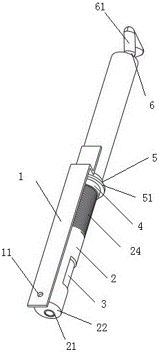
[0019] The device wire clip punching and positioning device of the present invention includes a main body rod 2, the main body rod 2 is cylindrical, the positioning ruler 1 is fixed on the main body rod 2, and the positioning ruler 1 can be fixed on the main body rod by rivets or screws. It can also be fixed by other means such as welding. There is a gap 7 between the positioning ruler 1 and the main body rod, the positioning ruler 1 front end is provided with a positioning hole 11, the lower edge of the positioning hole 11 and the front end face 23 of the main body rod are located on the same horizontal plane, and the front portion of the main body rod is provided with a groove 23 for positioning. The wheel 3 is placed in the groove 23, and the rotating rod 6 penetrates the cavity of the main body rod from the rear end of the main body rod 2 and enters the fixed cavity 31 on the positioning wheel 3, and the positioning wheel 3 is fixed in the groove 23, and the positioning whe...


PUM


Abstract

The invention discloses a device wire clip punching and positioning device, which includes a main body rod, the main body rod is cylindrical, a positioning ruler is fixed on the main body rod, and there is a gap between the main body rod and the front end of the positioning ruler is provided with a positioning hole. The lower edge of the positioning hole is at the same level as the front end of the main rod, and the front of the main rod is provided with a groove, and the positioning wheel is placed in the groove, and the rotating rod penetrates the cavity of the main rod from the rear end of the main rod and enters the positioning wheel The fixed cavity of the positioning wheel is fixed in the groove, and the positioning wheel rotates in the groove with the rotation of the rotating rod. The fixed cavity of the positioning wheel deviates from the center of the positioning wheel, and the fixed cavity is thicker on one side and thinner on the other. The invention can measure the position of the drip hole of the equipment line clamp and quickly locate and punch the hole. The position of the drip hole is accurate, which can effectively remove accumulated water and improve the reliability of the future operation of the equipment line clamp.

Description

technical field [0001] The invention relates to the technical field of electric power equipment, in particular to a hole-punching and positioning device for wire clips of equipment. Background technique [0002] Equipment clamps are commonly used on power equipment to connect the lead wires to the outlet terminals of electrical equipment (such as transformers, switches, switches, transformers, wall bushings, etc.). The outlet terminals of commonly used electrical equipment are copper and aluminum, and the bus lead-out wires are divided into aluminum stranded wires or steel-cored aluminum stranded wires. Correspondingly, equipment clamps are divided into aluminum equipment clamps and copper-aluminum transition equipment in terms of material. There are two series of wire clips. According to different installation methods and structural forms, equipment clamps are divided into two types: bolt type and compression type. [0003] The equipment clamp includes a connection part a...

Claims


Application Information

Patent Timeline
Patent Type & Authority Applications(China)
IPC IPC(8): H01R43/16
CPCH01R43/16
Inventor 荀鹏肖向波徐慧君王玉冰宫乳青刘霖
Owner 国网山东省电力公司乳山市供电公司
Learn More