
High voltage wire remote monitoring system

A remote monitoring system, high-voltage wire technology, applied in the direction of electrical components, circuit devices, overhead lines/cable equipment, etc.

Inactive Publication Date: 2018-07-20
ZHANGQIU POWER SUPPLY CO OF STATE GRID SHANDONG ELECTRIC POWER CO +1
View PDF4 Cites 0 Cited by
  • Summary
  • Abstract
  • Description
  • Claims
  • Application Information

AI Technical Summary

Problems solved by technology

[0005] The invention provides a remote monitoring system for high-voltage wires, which solves the technical problem of remotely and accurately locating fault points between adjacent iron towers, so that after grasping the precise location of the fault point, specific power supply and maintenance solutions can be provided to improve power supply quality and high-voltage Wire Repair Efficiency

Method used

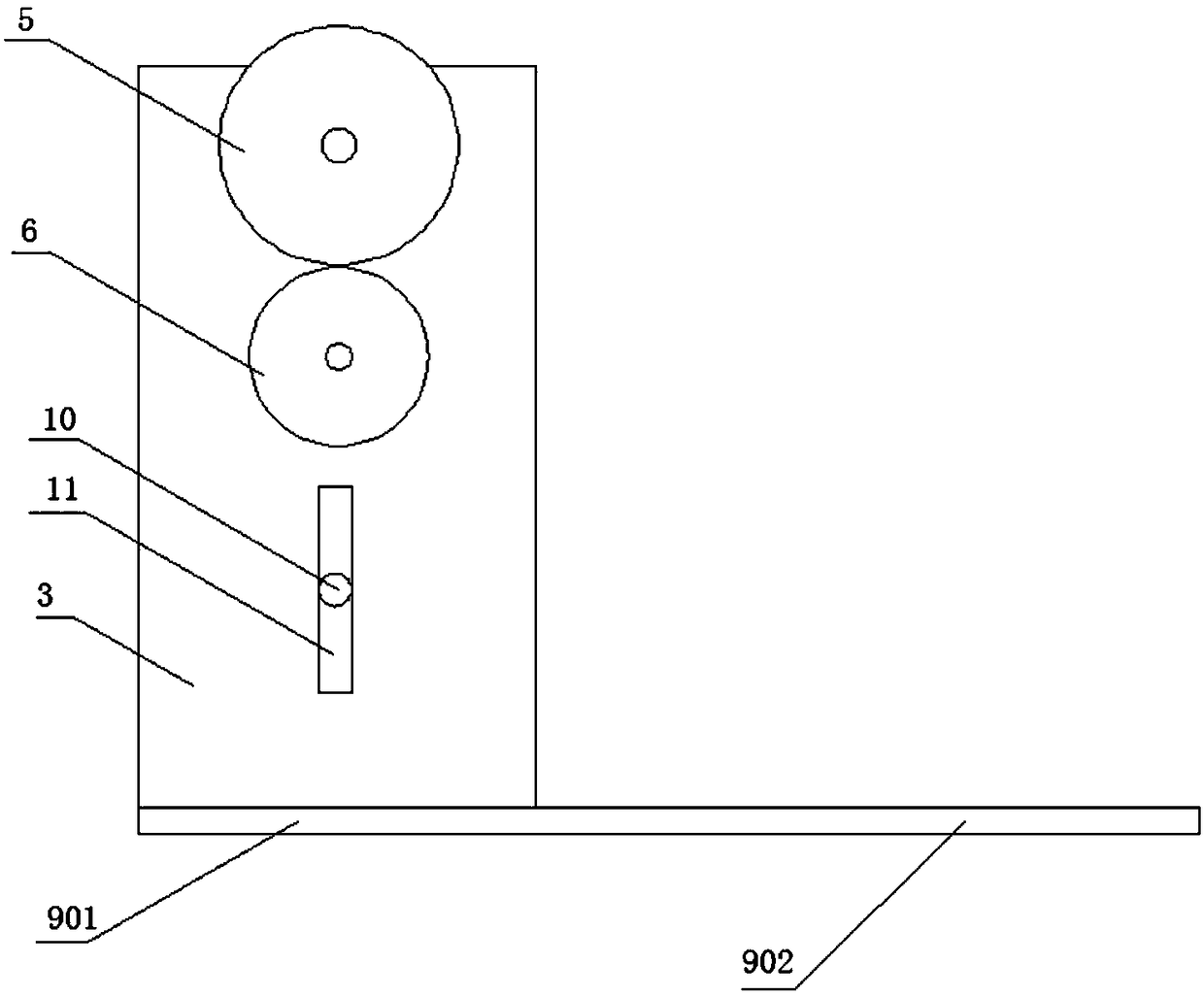
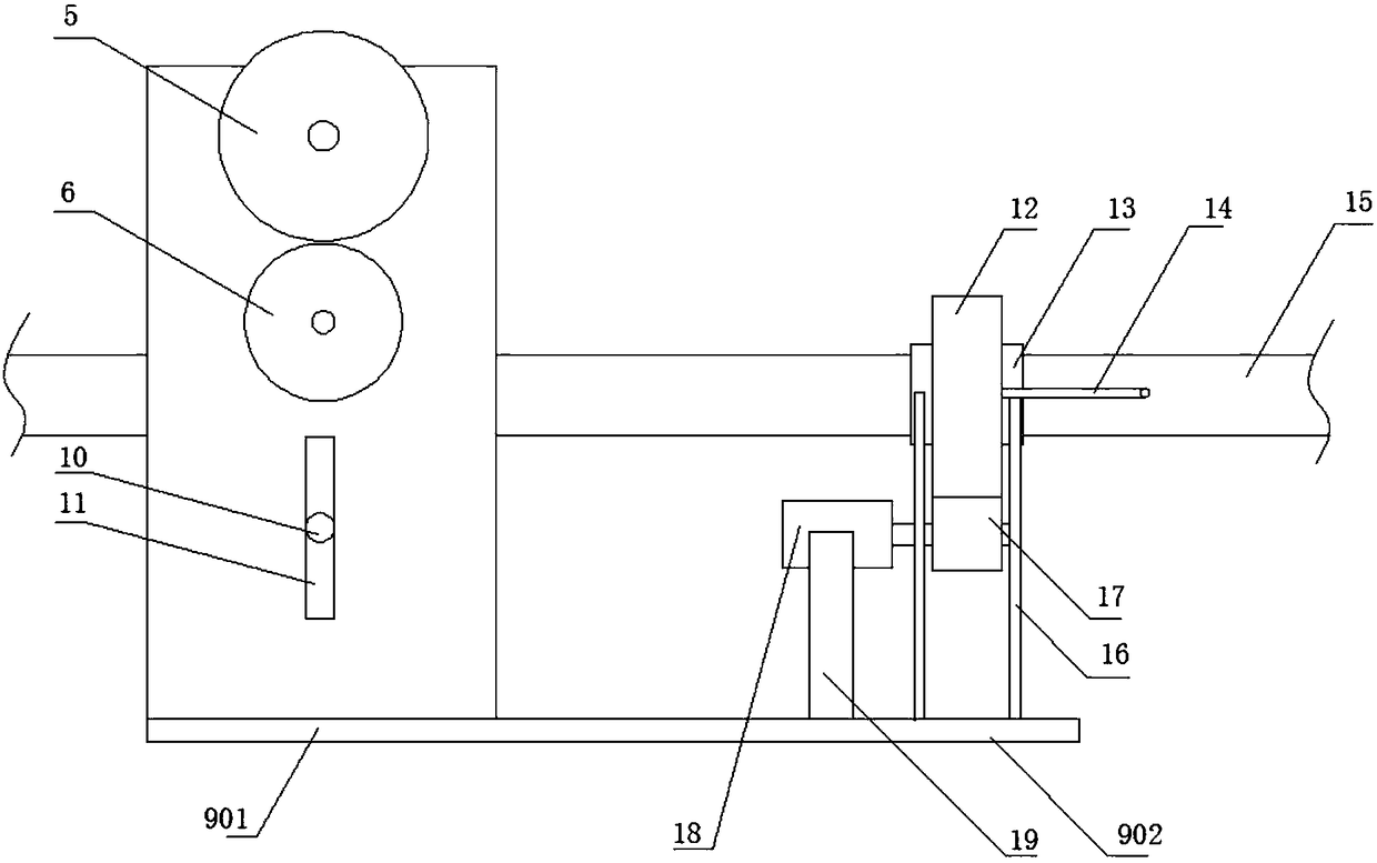

Image

  • High voltage wire remote monitoring system
  • High voltage wire remote monitoring system
  • High voltage wire remote monitoring system

Examples


Embodiment 1

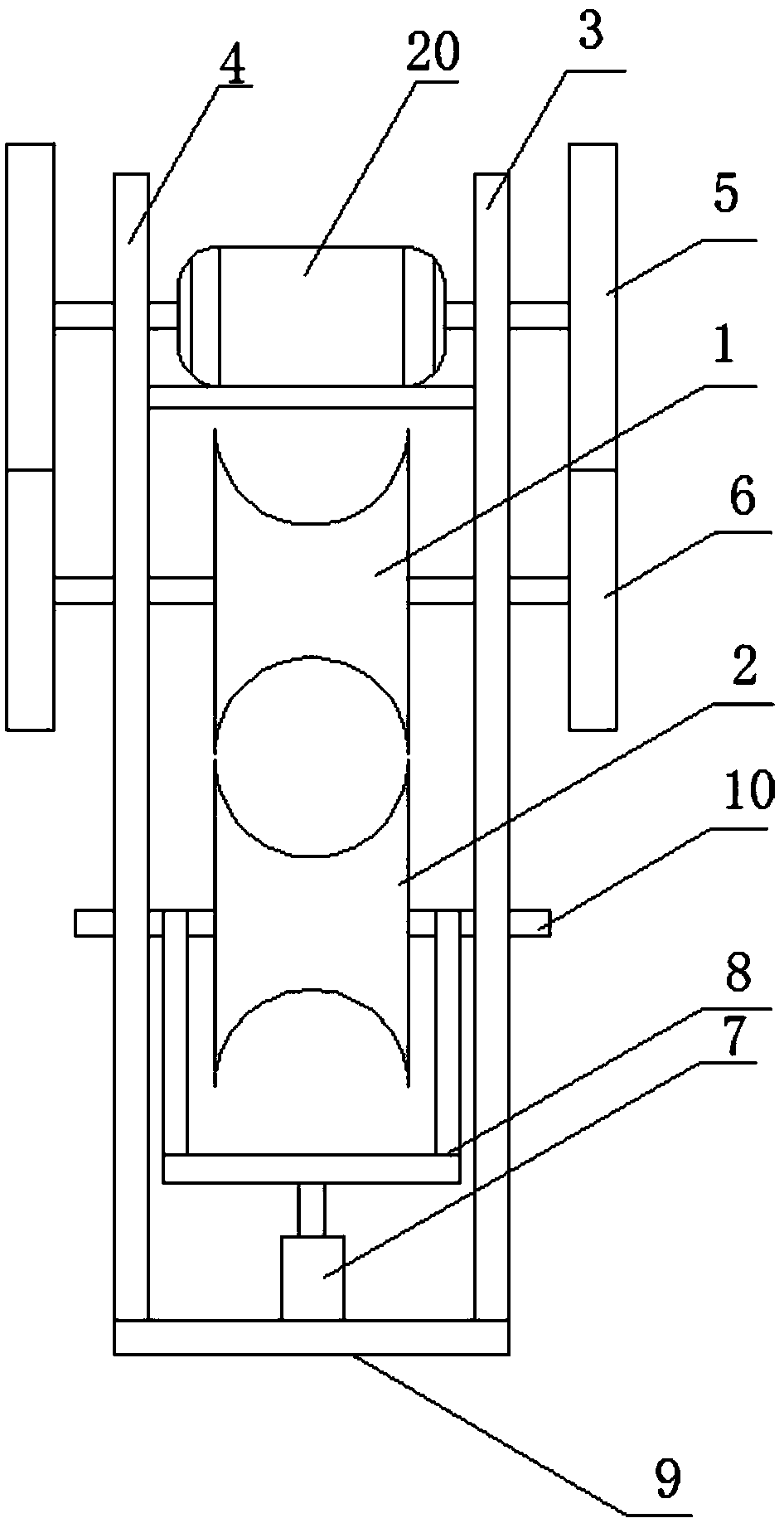
[0042] In this embodiment 1, if figure 1 , the running mechanism of the present invention is symmetrically arranged left and right, and the right side is used as an example for illustration. The traveling mechanism includes a roller set, which is composed of a first roller 1 and a second roller 2, and a gap is formed between them, and the gap is used to pass through high-voltage electric wires. The purpose is to use the first roller 1 and the second roller 2 to Squeeze the high-voltage wires, hang and fix the traveling mechanism as a whole on the high-voltage wires.

[0043] In this embodiment, in order to further optimize the extrusion and fixing effects of the first roller 1 and the second roller 2 on the high-voltage wires, see figure 1 , arc-shaped grooves are set on the extrusion peripheral surfaces of the first roller 1 and the second roller 2, so that the high-voltage wires can be partially embedded in the arc-shaped grooves, and the first roller 1 and the second rolle...

Embodiment 2

[0053] Compared with Embodiment 1, this embodiment differs in that: in this embodiment, the central control device and the remote monitoring center adopt CDMA mode to realize data interaction. In addition, the transmission between the two main transmission wheels of the biaxial motor and the two corresponding secondary transmission wheels of the first roller is through the track structure; the transmission between the runner 17 of the second power unit and the outer sleeve 12 is also through the track structure.


PUM


Abstract

The invention discloses a high-voltage wire surface defect detection device. The high-voltage wire surface defect detection device comprises a walking mechanism and a detection apparatus; the detection apparatus is installed on the walking mechanism; the walking mechanism comprises a base, a rolling wheel group and a first power device; the base includes a first side plate, a second side plate and a bottom plate; the first side plate and the second side plate are installed on the bottom plate; the rolling wheel group comprises a first rolling wheel and a second rolling wheel; a gap for clamping a wire is formed between the first rolling wheel and the second rolling wheel; the first rolling wheel is arranged between the first side plate and the second side plate; the second rolling wheel is installed on a lifting mechanism which controls the lifting and descending of the second rolling wheel; the lifting mechanism is installed on the base; and the first power device drives the first rolling wheel to rotate and is installed on the base. With the high-voltage wire surface defect detection device of the invention adopted, detection personnel can directly observe the condition of each position of a high-voltage wire and accurately determine the specific location of a detect point on the high-voltage wire.

Description

technical field [0001] The invention belongs to the field of high-voltage wire surface detection machinery, and in particular relates to a high-voltage wire remote monitoring system. Background technique [0002] Long-distance transmission of high-voltage electric energy in the field requires the use of high-voltage wires, which are suspended through iron towers. Because the distance between the iron towers is relatively long, the large-span high-voltage wires between the iron towers are prone to repeated pulling and twisting under harsh field conditions, resulting in local tearing on the surface of the high-voltage wires. If not found and repaired in time , Eventually causing high-voltage wires to break unexpectedly, power supply accidents occur, affecting residents and industrial electricity consumption, and causing harm to local animals and plants on the ground, and even pedestrians. [0003] At present, the early warning of defects in high-voltage wires is mainly throug...

Claims


Application Information

Patent Timeline
Patent Type & Authority Patents(China)
IPC IPC(8): H02J13/00H02G1/02
CPCH02G1/02H02J13/00001
Inventor 孙茂森田振友姜峰张宏鸣高向刘蕾高波李悦军
Owner ZHANGQIU POWER SUPPLY CO OF STATE GRID SHANDONG ELECTRIC POWER CO
Learn More