Supercharge Your Innovation With Domain-Expert AI Agents!

Dental implant

A technology for oral implants and implants, which is applied in dental implants, medical science, dentistry, etc., can solve problems such as breakage, inability to properly ensure the thickness of elastic fastening pillars 22, and inability to design allowable bending space, etc., to ensure the structure The effect of stability

Inactive Publication Date: 2016-08-10
金亨宇 +2
View PDF8 Cites 3 Cited by
  • Summary
  • Abstract
  • Description
  • Claims
  • Application Information

AI Technical Summary

Problems solved by technology

[0010] However, as the diameter of the lower fastening shaft portion of the above-mentioned base 20 becomes smaller as described above, the width of the allowable bending space W for accommodating the bending action of the elastic fastening strut needs to be greater than the sum of the widths of the fastening parts (2T). If there is a width T of the fastening portion for ensuring proper fastening force, it is also necessary to have a minimum allowable bending space W that must be ensured between the fastening struts 22, so the required elastic tightness cannot be ensured. Solid pillar 22 thickness
[0011] That is, the elastic fastening strut 22 cannot be bent without the slot 26, and when a certain size of the slot 26 (that is, a space allowed for bending) is ensured, the lower fastening shaft portion with a smaller diameter cannot properly ensure elasticity. Thickness of fastening strut 22
[0012] If the fastening pillar 22 cannot ensure a proper thickness as described above, if figure 1 As shown, when a lateral external pressure P is applied to the implant from the outside, the connection portion of the fastening pillar 22 extending from the abutment 20 will be relatively weak in structure, and cracks K or damage will often occur, so that proper maintenance and tightness cannot be ensured. Solid force
[0013] Under the structure of the lower fastening shaft part of the limited diameter abutment fastened on the small diameter implant (fixture) used to implant the thinner alveolar bone as mentioned above, the prior art cannot design a Oral implants that allow for bending space of the fastening part of sufficient size, are sufficient to withstand lateral external pressure, and ensure the thickness of the elastic fastening strut 22 at a level that can have a proper fastening force

Method used


Image

  • Dental implant
  • Dental implant
  • Dental implant

Examples


Embodiment Construction

[0038] Preferred embodiments of the present invention will be described in detail below in conjunction with the accompanying drawings.

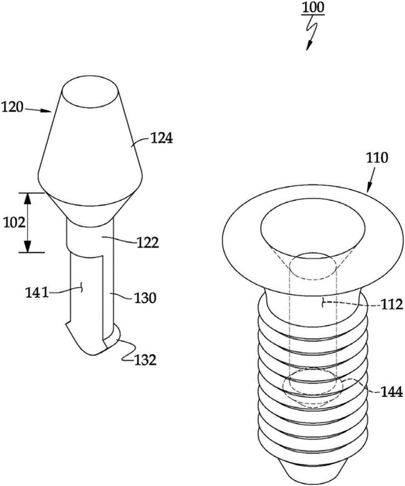
[0039] Such as figure 2 As shown, the oral implant 100 according to the present invention includes: an implant 110 with a shaft hole 112 formed on the top and a guide groove formed inside to be implanted into the alveolar bone; and an abutment 120 inserted into the shaft hole 112 of the implant 110 In addition, it is elastically combined with the lower fastening shaft 122 of the above-mentioned implant 110 and the upper installation part 124 of the installation prosthesis (not shown). The basic structure as previously described is then the same as the existing structure.

[0040] However, different from the existing structure, the structure of the present invention is as follows. The above-mentioned abutment 120 only forms an elastic fastening strut 130 on the lower fastening shaft 122, and the elastic fastening strut 130 has a shaft hole 1...


PUM


Abstract

The present invention relates to a dental implant related to a prosthetic tooth, and to a dental implant having a fixing structure in which a fixture and an abutment are resiliently coupled, wherein a plurality of resilient legs are formed by means of cutout portions in a lower fastening shaft portion of the abutment, the plurality of resilient legs includes fastening means such as a fastening recess, a fastening projection, or a fastening ledge, and is characterized by including resilient legs having two functions and consists of resiliently fastening legs fastened to a fastening portion corresponding to the fixture, and non-fastened supporting legs that do not have the fastening means.

Description

technical field [0001] The present invention relates to an oral implant for artificial teeth. More specifically, the oral implant has a fastening structure in which the fixture and the abutment are elastically combined. The lower fastening shaft portion of the abutment (abutment) of the fixture is formed with a plurality of elastic struts formed by cutting grooves at the same time, and has elastic parts for fastening such as fastening protrusions or fastening grooves or fastening flanges. Fastening struts and non-fastening support struts that do not have fastening projections, fastening grooves, or fastening flanges or other fastening support struts, or multiple elastic fastening struts that vary the vertical position of the fastening portion , so that the size of the required allowable bending space can be reduced, and the elastic fastening strut formed on the lower fastening shaft portion of the abutment of the fixture (fixture) whose diameter is relatively smaller than that...

Claims


Application Information

Patent Timeline
Patent Type & Authority Applications(China)
IPC IPC(8): A61C8/00A61C13/277
CPCA61C8/0057A61C8/0062A61C8/0048A61C8/0051A61C13/277A61C8/00A61C8/0086
Inventor 金亨宇金均焕金善英
Owner 金亨宇
Features
  • R&D
  • Intellectual Property
  • Life Sciences
  • Materials
  • Tech Scout
  • Unparalleled Data Quality
  • Higher Quality Content
  • 60% Fewer Hallucinations
Learn More