
Laminating apparatus

A lamination device, lamination roller technology, applied in the lamination device, lamination, rolling mill control device, etc., can solve the problems of incorrect assembly of products, insufficient lamination pressure, loss of performance, etc., to achieve excellent reliability, structure The effect of economy and simple structure

Active Publication Date: 2016-08-10
MANZ ITAL
View PDF5 Cites 3 Cited by
  • Summary
  • Abstract
  • Description
  • Claims
  • Application Information

AI Technical Summary

Problems solved by technology

[0005] If the lamination pressure (which is always equal to the ratio of the lamination pressure applied by the roller to the area subjected to this force) is not constant, there will be insufficient lamination pressure for the product (in some areas), so that the product will not be correct. assembly, and / or subjecting the product (in other areas) to excessive lamination pressure, which may subsequently cause damage to the product, especially to the separation membrane, whereby the latter may be lost (at least in part) necessary for the manufacture of high-quality electrical energy accumulation devices performance

Method used


Image

  • Laminating apparatus
  • Laminating apparatus
  • Laminating apparatus

Examples


Embodiment Construction

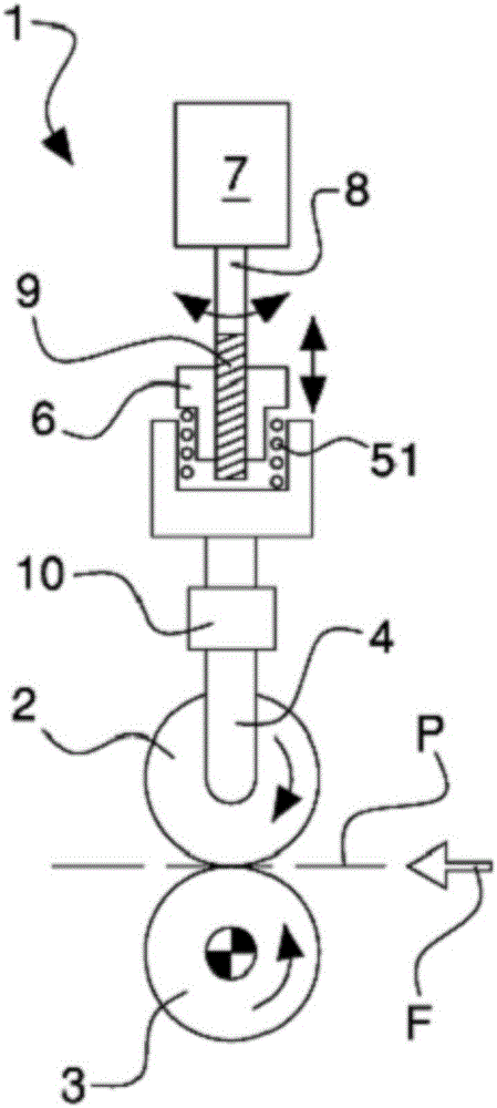
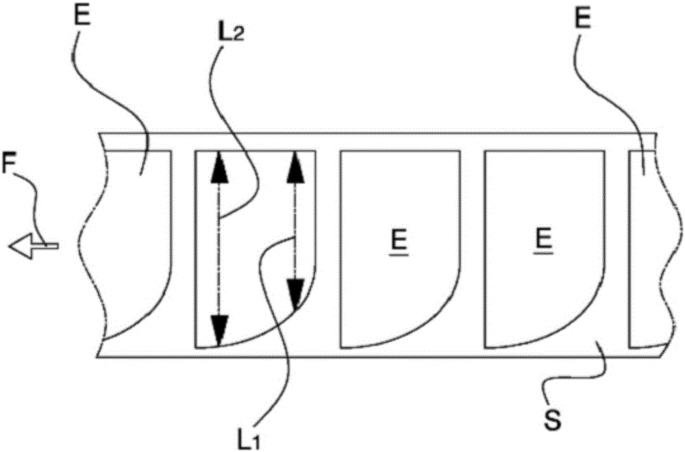
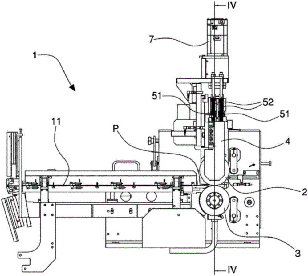
[0021] refer to the above Figure 1 to Figure 6 , numeral 1 denotes the whole of a lamination device which can be used in particular for the manufacture of electric energy accumulating devices (batteries, capacitors, etc.). In particular, the lamination device 1 can be used to couple at least one flat electrode E of non-rectangular shape with at least one separation membrane S. For greater clarity of illustration, the same reference numerals are used in the drawings to designate similar parts of several example embodiments.

[0022] Apparatus 1 comprises a first (upper) lamination roll 2 and a second (lower) lamination roll 3 coupled together and facing each other to define The lamination zone that extends between the rolls. In particular, the two lamination rollers 2 and 3 have axes of rotation parallel (horizontal) to each other. The lamination zone may extend widthwise in a direction parallel to the axes of the two lamination rolls 2 and 3 .

[0023] The object to be la...


PUM


Abstract

There is described a laminating apparatus for coupling electrodes of non-rectangular shape with a separating film for the manufacture of electric energy accumulating devices, wherein a pair of laminating rollers has a roller driven by elastic means loaded with a variable force adjusted by an endless screw conveyor controlled by a brushless motor, during the passage of the electrodes, so as to vary the laminating force according to the width of the electrode laminated instant by instant, in order for the laminating pressure to remain almost constant.

Description

Background of the invention [0001] The present invention relates to a lamination device, in particular to a device for coupling an electrode and a separation membrane by lamination. [0002] In particular but not exclusively, the device can be used in the manufacture of electrical energy accumulating devices. [0003] In particular, reference is made to lamination roller arrangements which may advantageously be used for laminating flat objects of non-rectangular shape. [0004] A problem with lamination rollers for laminating objects of non-rectangular shape is ensuring that the lamination pressure remains constant over the entire surface of the object to be laminated. Indeed, when an object of non-rectangular shape passes between two lamination rollers, the width of the object subjected to the lamination force exerted by the rollers varies (in real time) according to the shape of the object. [0005] If the lamination pressure (which is always equal to the ratio of the lami...

Claims


Application Information

Patent Timeline
Patent Type & Authority Applications(China)
IPC IPC(8): H01M10/04B21B37/00B65H20/00H01M4/02
CPCH01M10/0404H01M10/0413H01M10/0436Y02E60/10Y02P70/50B32B37/0015B32B37/0023B32B37/223H01M4/02H01M10/0585B21B37/60B32B37/0053B32B37/10B32B37/1054B65H2404/1441B65H2511/224H01G9/0029H01M6/005H01M6/02
Inventor 马西米利亚诺·赛尔马可·维瓦雷利
Owner MANZ ITAL
Learn More