Combined trigger type friction stir plug brazing repair welding method and its welding tool

A friction stir, triggering technology, applied in welding equipment, manufacturing tools, non-electric welding equipment, etc., can solve problems such as cracks, incomplete keyhole filling, and reduced strength of repair welding joints, achieving high strength and improving repair welding. The effect of seam quality and workpiece deformation is small

Active Publication Date: 2018-03-27
安徽万宇机械设备科技有限公司
View PDF7 Cites 0 Cited by
  • Summary
  • Abstract
  • Description
  • Claims
  • Application Information

AI Technical Summary

Problems solved by technology

[0005] The present invention solves the problem that defects such as incomplete filling and cracks are prone to occur at the bottom of the keyhole during the repair welding process of the existing friction stir welding, which leads to the reduction of the strength of the repair welded joint, especially for repairing and repairing defects in the hollow or unsupported state. Hole repair welding provides a combined trigger type friction stir plug brazing repair welding method and its welding tools

Method used


Image

  • Combined trigger type friction stir plug brazing repair welding method and its welding tool
  • Combined trigger type friction stir plug brazing repair welding method and its welding tool
  • Combined trigger type friction stir plug brazing repair welding method and its welding tool

Examples


specific Embodiment approach 1

[0023] Specific implementation mode one: combine figure 1 , figure 2 , image 3 and Figure 5 Describe this implementation mode, this implementation mode is realized through the following steps:

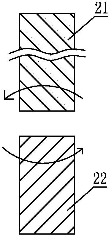
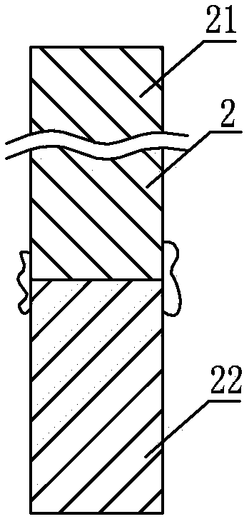
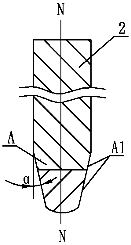
[0024] Step 1, preparing the stirring body 2: the stirring body 2 is divided into upper and lower parts, the upper part of the stirring body adopts a metal rod 21, and the lower part of the stirring body adopts a zinc-aluminum bar material 22, see figure 1 , the material of the metal rod 21 is the same as that of the parts to be repaired, and the metal rod 21 and the zinc-aluminum rod 22 are set up and down and connected together, see figure 2 , the metal on the surface of the stirring body 2 is removed by mechanical processing, and the lower end of the stirring body 2 is processed into a truncated conical shape A, the bottom of the truncated conical shape A is a spherical surface, and the truncated conical shape A is the stirring needle A, see image 3 , the upper part of the ...

specific Embodiment approach 2

[0028] Specific implementation mode two: combination figure 2 This embodiment is described. In this embodiment, the metal rod 21 and the zinc-aluminum rod 22 are welded together by friction welding in the first step. Other steps are the same as in the first embodiment.

specific Embodiment approach 3

[0029] Specific implementation mode three: combination Figure 4 Describe this embodiment, this embodiment is that in step 1, the metal rod 21 and the zinc-aluminum rod 22 are connected together by means of threaded connection, wherein the lower end surface of the metal rod 21 is an internal thread, and the upper end surface of the zinc-aluminum rod 22 is external thread. Other steps are the same as in the first embodiment.


PUM


Abstract

The invention provides a combined triggering type friction stir plug braze welding and repair welding method and a welding tool thereof. The method comprises the following steps: 1, machining the lower end of a stirring body 2 into a stirring needle which is conical, wherein the upper part of the stirring needle is made of a metal material, and the lower part of the stirring needle is made of an aluminum zinc material; 2, determining the size of the stirring needle; 3, positioning a key hole required to be repaired; and 4, in a braze welding and repair welding process of a friction stir plug, rubbing the stirring needle with the material of the inner wall of the key hole to be subjected to repair welding, rubbing an aluminum zinc bar with the inner wall of the key hole in advance at the low temperature so as to plastify, continuing carrying out friction stir downwards by using a metal bar, and rubbing the upper part of the stirring needle of the metal bar with the inner wall of the key hole to generate heat so that the key hole which needs to be subjected to repair welding and has been filled with the aluminum zinc bar is fully filled with the aluminum zinc bar. According to the welding tool, the stirring body is arranged in a clamping hole of a clamping body, circumferential surfaces of the stirring needle at the upper end and the stirring needle at the lower end are conical surfaces, the stirring needle at the upper end and the stirring needle at the lower end form the stirring needle, and the stirring needle is exposed out of the lower end surface of a lower cylinder. The combined triggering type friction stir plug braze welding and repair welding method and the welding tool thereof are used for repair welding of the friction stir welding key hole.

Description

technical field [0001] The invention relates to a method for repairing friction stir plug welding, in particular to a combined trigger type friction stir plug brazing repair method and welding tools. Background technique [0002] Since the invention of Friction Stir Welding (FSW) by the British Welding Institute (TWI) in 1991, this technology has many advantages compared with traditional fusion welding methods in the field of light alloy joining, such as joint fatigue performance, tensile properties Good, the residual stress and deformation after welding are small, and welding defects such as cracks and pores can be avoided. At the same time, it can significantly reduce costs and save materials, and has attracted widespread attention. However, in the case of improper process parameters or conditions, defects such as incomplete filling, incomplete penetration and discontinuous root are prone to occur, thereby reducing the performance of the weld. Similarly, the keyhole left ...

Claims


Application Information

Patent Timeline
Patent Type & Authority Patents(China)
IPC IPC(8): B23K20/12B23K20/24
CPCB23K20/122B23K20/1255B23K20/24
Inventor 万龙李旭吕宗亮黄体方谢聿铭黄永宪
Owner 安徽万宇机械设备科技有限公司
Why Eureka
Try Eureka