Ball-in-ball machining fixture and utilization method thereof

A ball-in-the-ball and fixture technology, applied in the direction of manufacturing tools, metal processing equipment, metal processing machinery parts, etc., can solve the problems of cumbersome preparation work, low efficiency, positioning error, etc., to ensure drilling position accuracy, simple operation, The effect of improving efficiency

Inactive Publication Date: 2016-08-17
DALIAN NATIONALITIES UNIVERSITY
View PDF7 Cites 5 Cited by
  • Summary
  • Abstract
  • Description
  • Claims
  • Application Information

AI Technical Summary

Problems solved by technology

[0002] Ball-in-the-ball is drilled on the outer surface of the sphere, so that it falls off inside to form another sphere that can move freely; the preparation work in the previous manufacturing method is cumbersome. First, draw lines and mark points on the surface of the outer sphere to determine the hole. The machining position, and then use the three-jaw chuck on the machine tool to process the hole. During the machining process, the three-jaw chuck must be loosened several times to rotate the sphere, and the relative position of the tool and the marked point on the surface of the sphere must be manually checked to ensure that the tip of the tool or The center and the hole marking point are collinear; the above calibration work must be repeated every time a hole is processed, the efficiency is low, and there are positioning errors

Method used


Image

  • Ball-in-ball machining fixture and utilization method thereof
  • Ball-in-ball machining fixture and utilization method thereof
  • Ball-in-ball machining fixture and utilization method thereof

Examples


Embodiment Construction

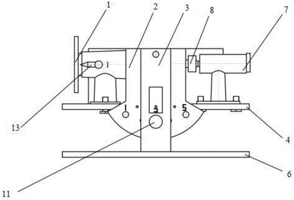
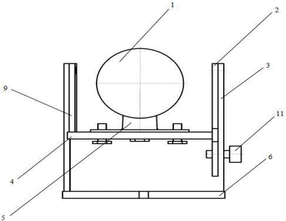
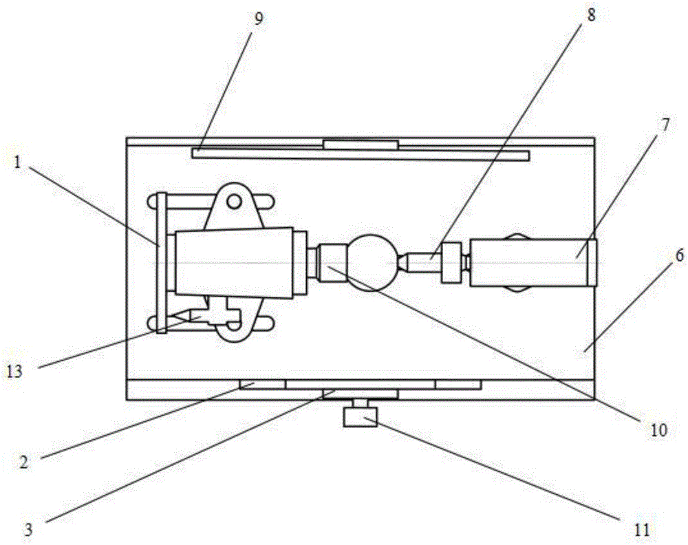
[0055] The present invention will be further described below in conjunction with the accompanying drawings. like Figure 1-4 As shown, a processing jig for a ball-in-a-ball includes an indexing plate 1, a positioning plate 2, a front support vertical plate 3, a supporting plate 4, an adjustable support seat 5, a bottom plate 6, a top seat 7, a rotary top 8, a fixed Plate 9, rear support vertical plate and taper shank positioning seat 10;

[0056] The front support vertical plate 3 is installed on the edge of the front side of the base plate 6, and the positioning plate 2 is installed on the front support vertical plate 3 through the optical axis A, and can rotate around the optical axis A; the rear support vertical plate The plate is installed on the edge of the rear side of the bottom plate 6, and the fixed plate 9 is installed on the rear supporting vertical plate through the optical axis B, and can rotate around the optical axis B;

[0057] The supporting plate 4 is fixed...


PUM


Abstract

The invention discloses a ball-in-ball machining fixture and a utilization method thereof. The fixture comprises an index plate, a positioning plate, a front vertical supporting plate, a supporting plate, an adjustable supporting seat, a bottom plate, a centre seat, a live centre, a fixing plate, a rear vertical supporting plate and a taper shank positioning seat. The index plate which is a disc is mounted on the taper shank positioning seat through a rotating shaft and capable of rotating around the rotating shaft by 360 degrees; 20 positioning holes are uniformly and annularly distributed in the index plate; the positioning plate is a sector plate, and five positioning holes are uniformly distributed in the positioning plate along an arc line. The ball-in-ball machining fixture has advantages that firstly, marking of lines and points on the surface of a ball is avoided; secondly, repeated correction of a relative position of a tool to drilling points on the surface of the ball in machining of each hole is avoided; thirdly, machining and manufacturing efficiency is improved, and errors of manual correction and positioning are avoided; fourthly, simplicity in operation, structural stability, accuracy in positioning and convenience in demounting and transporting are realized. Ball-in-ball rotation angles are positioned by cooperation of the live centre and the index plate, and accordingly precision of drilling positions is guaranteed.

Description

technical field [0001] The invention relates to a ball-in-ball processing technology, in particular to a ball-in-ball processing fixture. Background technique [0002] Ball-in-the-ball is drilling on the outer surface of the sphere, so that it falls off inside to form another sphere that can move freely; the previous processing and manufacturing methods are more cumbersome to prepare. First, draw lines and mark points on the surface of the outer sphere to determine the hole. The processing position, and then use the three-jaw chuck on the machine tool to process the hole. During the processing, the three-jaw chuck must be loosened many times to rotate the sphere, and the relative position of the tool and the marked point on the surface of the sphere must be manually checked to ensure that the tip of the tool or The center is collinear with the hole marking point; the above-mentioned proofreading work must be repeated every time a hole is processed, the efficiency is low, and...

Claims


Application Information

Patent Timeline
Patent Type & Authority Applications(China)
IPC IPC(8): B23Q3/06
CPCB23Q3/062
Inventor 陈兴文邵强王立新宫永伟郑琳陈剑伟段立民赵志强安泓达
Owner DALIAN NATIONALITIES UNIVERSITY
Why Eureka
Try Eureka