A film cutting machine with the function of protecting the cutter

A technology of film cutting machine and cutter, which is applied in metal processing and other directions, can solve the problems of cutter damage, inertial idling of film roll, etc., and achieve the effect of avoiding collision

Active Publication Date: 2018-01-26
ANQING XINSHUN PLASTIC CO LTD
View PDF7 Cites 0 Cited by
  • Summary
  • Abstract
  • Description
  • Claims
  • Application Information

AI Technical Summary

Problems solved by technology

[0005] The purpose of the present invention is to solve the defects of the film roll of the film cutting machine in the prior art due to inertia idling and cutter damage, and to provide a film cutting machine with the function of protecting the cutter to solve the above problems

Method used


Image

  • A film cutting machine with the function of protecting the cutter
  • A film cutting machine with the function of protecting the cutter
  • A film cutting machine with the function of protecting the cutter

Examples


Embodiment 1

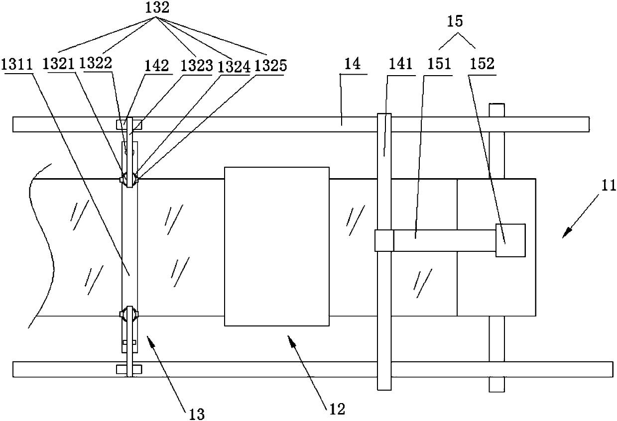
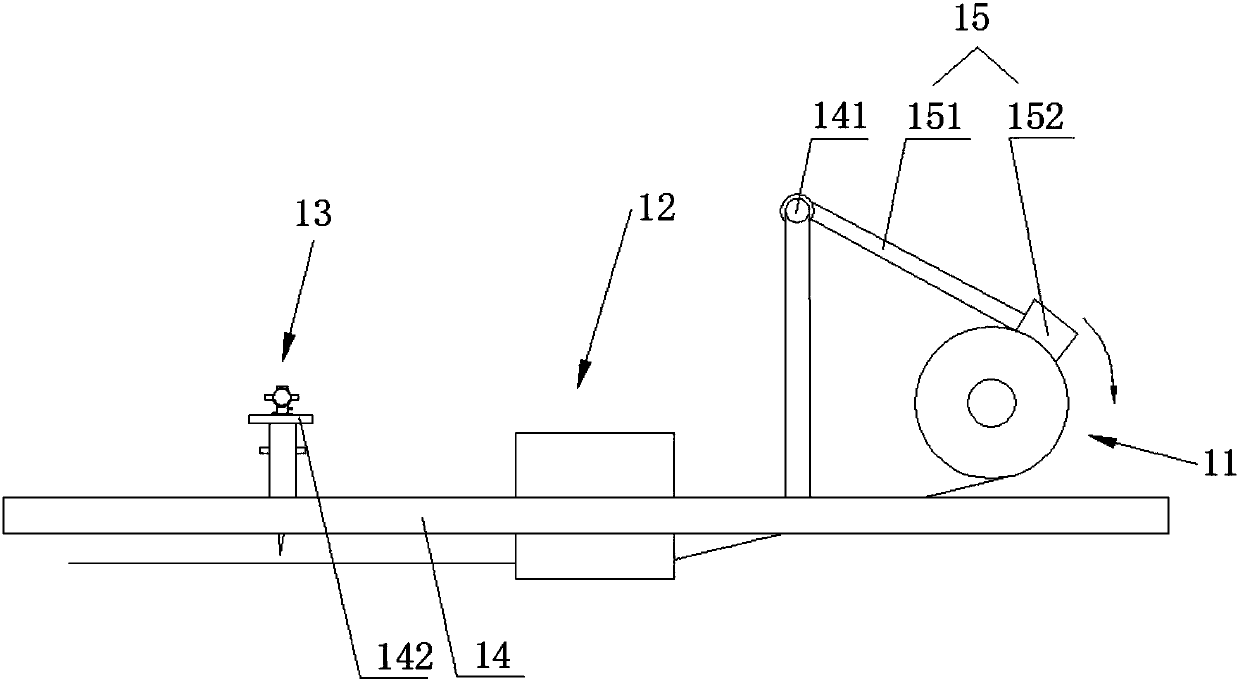
[0022] Such as figure 1 , figure 2 As shown, a film cutting machine with the function of protecting the cutter includes a frame; the frame 14 is provided with a film roll 11, a film feeding device 12, and a film cutting device 13; the film feeding device 12 cuts the film of the film roll 11 Is conveyed to the film cutting device 13; the frame 14 is also provided with a pressing device 15 that controls the inertial rotation speed of the film roll 11; the pressing device 15 is fixed on the frame 14 in rotation; the film cutting device 13 includes a cutting knife 131 and The limiting portion 132 of the cutting knife 131 is protected; the limiting portion 132 is fixed at one or both ends of the cutting knife 131.

[0023] In the present invention, a limiting portion 132 is provided at both ends of the cutting knife 131.

[0024] The film provided by the present invention is drawn out from below the film roll 11, and is conveyed to the film cutting device 13 through the film feeding de...

Embodiment 2

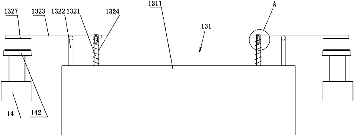
[0030] Such as image 3 , Figure 4 As shown, as a preferred solution of Embodiment 1, in order to make the falling and resetting process of the cutter 131 more gentle, the limit rod 1323 of the present invention is connected with the first vertical rod 1321 and the second vertical rod 1322 by rotation. Specifically: the upper end of the first vertical rod 1321 has a U-shaped groove, and waist-shaped holes 1326 are formed on the two side walls of the U-shaped groove; the end of the limit rod 1323 is provided with a through hole; the limit rod 1323 is clamped in the U shape In the groove and fixed by the pin 1325. The rod body of the limit rod 1323 and the second vertical rod 1322 may be connected by rotation. The limiting rod 1323 is parallel to the rotation axis of the first vertical rod 1321 and the rotation axis of the second vertical rod 1322 and cuts perpendicular to the cutting surface of the cutter 131. When the cutter 131 is lowered, the limit rod 1323 is restricted b...

Embodiment 3

[0032] Such as Figure 4 As shown, as a preferred solution of Embodiment 2, the present invention further includes an elastic member 1324 on the rod body of the first vertical rod 1321; the upper and lower ends of the elastic member 1324 are respectively restricted by the knife back 1311 and the limit rod 1323, As a result, the elastic member 1324 pushes the pin shaft 1325 on the uppermost part of the waist hole. The elastic member 1324 provided by the present invention is a compression spring or other elastic components with equivalent functions. With this design, when the cutter 131 is lowered, the free end of the limit rod 1323 is lifted by the baffle 142. With the second vertical rod 1322 as the fulcrum, the connecting end of the limit rod 1323 and the first vertical rod 1321 is lowered and pressed The spring is compressed and the compression spring is compressed. After the film is cut, the compression spring is reset, which drives the cutter 131 to quickly reset, avoidin...


PUM


Abstract

The invention provides a film cutting machine with a cutter protection function. The film cutting machine comprises a cutter and limiting parts for protecting the cutter, wherein the limiting parts are fixed at one end or two ends of the cutter and comprise first vertical rods and second vertical rods; the first vertical rods and the second vertical rods are fixed at positions, close to the end parts, of the cutter back; the limiting parts further comprise limiting rods which are fixed on the first vertical rods and the second vertical rods; the other ends of the limiting rods are free ends; a transverse baffle is fixed at the position, which is placed at the end part of the cutter, on a rack; when the cutter drops to a set value, the limiting rods are limited by the baffle. Compared with the prior art, the film cutting machine disclosed by the invention has the advantages that after running on equipment for certain time, the film cutting machine is worn to a certain extent, and the dropping position of the cutter excurses, which makes a cutterhead be damaged; to protect the cutterhead of the cutter, the limiting parts are provided; due to the arrangement of the limiting rods on the cutter back and the arrangement of the baffle for limiting the limiting rods on the rack, the dropping speed of the cutter which cuts a film can be controlled in time, to avoid collision of the cutterhead with a hard object below.

Description

Technical field [0001] The invention relates to the technical field of plastic film production, in particular to a film cutting machine with the function of protecting a cutting knife. Background technique [0002] At present, packaging bags are widely used in daily life and work due to their convenience and simplicity during use and carrying. Plastic products include polyethylene plastic products, polypropylene plastic products and polyvinyl chloride plastic products. These plastic products can not only protect products and facilitate transportation, but also promote sales and beautify products. [0003] The plastic film is blown, printed, and rewinded, and then cut by a film cutting machine to form a finished product for sale. The traditional film cutting machine generally uses an intermittent feed mechanism to transport the film from the film roll to the film cutting device. In actual work, after the intermittent feed mechanism pulls the film, the film roll rotates, and the i...

Claims


Application Information

Patent Timeline
Patent Type & Authority Patents(China)
IPC IPC(8): B26D1/08B26D7/02B26D7/22B26D7/26
CPCB26D1/085B26D7/015B26D7/025B26D7/22B26D7/2614B26D7/2628
Inventor 汪俊
Owner ANQING XINSHUN PLASTIC CO LTD
Why Eureka
Try Eureka