Independent suspension system for super-heavy chassis

An independent suspension, super heavy-duty technology, applied in the field of suspension system, can solve the problems of high reliability, high height, small stroke, etc., and achieve the effect of meeting the needs of high maneuvering, coordinating motion relations, and reasonable layout

Active Publication Date: 2016-08-17
BEIJING INST OF SPACE LAUNCH TECH +1
View PDF6 Cites 19 Cited by
  • Summary
  • Abstract
  • Description
  • Claims
  • Application Information

AI Technical Summary

Problems solved by technology

[0004] In order to solve the problem that the suspension system in the prior art cannot guarantee high reliability when passing bad roads due to its small stroke and high height, the present invention provides an independent suspension system for super-heavy-duty chassis. There is an axle, and the two ends of the axle are symmetrically equipped with an upper cross arm assembly, a lower cross arm assembly and an oil-pneumatic spring, wherein one end of the upper cross arm assembly is connected to the swing arm of the vehicle frame through the first bearing structure The bracket is connected, and the upper cross arm assembly can be rotated on the axis of the first bearing structure, and one end of the lower cross arm assembly is connected with the swing arm bracket of the vehicle frame through the second bearing structure, and the lower cross arm The assembly can rotate on the axis of the second bearing structure, the other end of the upper cross arm assembly is connected to the upper end of the steering knuckle through the first ball joint device, and the other end of the lower cross arm assembly is connected through the second ball joint The device is connected to the lower end of the steering knuckle; the upper lug of the oil-pneumatic spring is connected to the oil-pneumatic spring bracket on the frame through the first joint bearing structure, and the lower end lug of the oil-pneumatic spring is connected to the lower cross arm assembly through the second joint bearing structure

Method used


Image

  • Independent suspension system for super-heavy chassis
  • Independent suspension system for super-heavy chassis
  • Independent suspension system for super-heavy chassis

Examples


Embodiment Construction

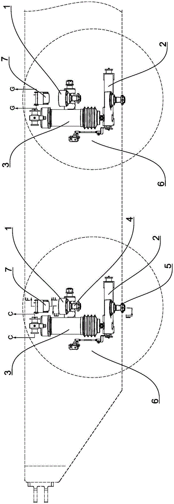
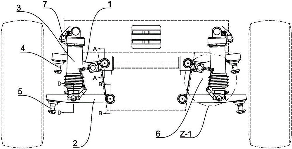
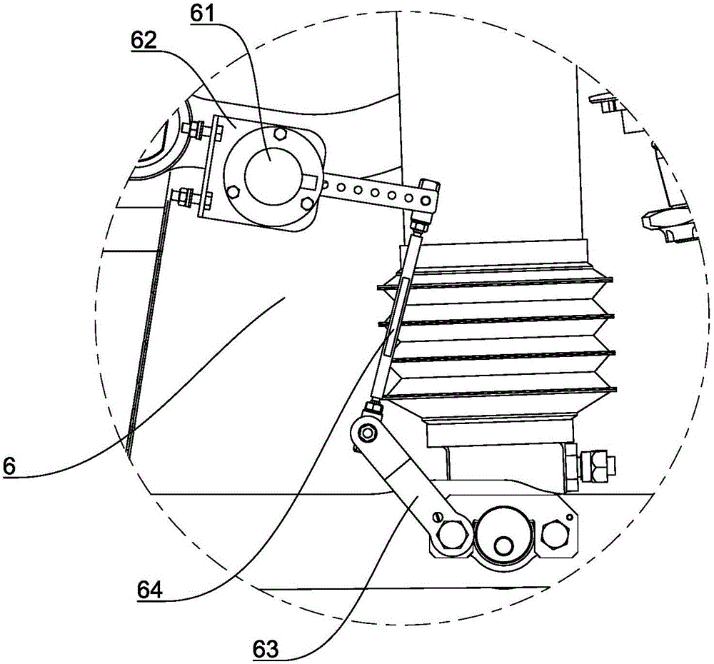
[0036] Such as Figure 1 to Figure 3 A specific embodiment of an independent suspension system for a super-heavy chassis is shown, which generally includes an upper cross arm assembly 1 , a lower cross arm assembly 2 and an oil-pneumatic spring 3 arranged symmetrically at both ends of the axle. One end of the upper cross arm assembly 1 is connected to the swing arm support of the vehicle frame through the first bearing structure, and the upper cross arm assembly 1 can perform a rotary motion on the axis of the first bearing structure, so that the lower cross arm assembly One end of the 2 is connected to the swing arm bracket of the vehicle frame through the second bearing structure, and the lower cross arm assembly 2 can be rotated on the axis of the second bearing structure, and the other end of the upper cross arm assembly 1 One end is connected with the upper end of the steering knuckle through the first ball hinge device 4 , and the other end of the lower cross arm assembl...


PUM


Abstract

The invention discloses an independent suspension system for a super-heavy chassis. The independent suspension system for the super-heavy chassis comprises upper cross arm assemblies, lower cross arm assemblies and hydro-pneumatic springs, wherein the upper cross arm assemblies, the lower cross arm assemblies and the hydro-pneumatic springs are symmetrically arranged at the two ends of an axle. One end of each upper cross arm assembly is connected with a swing arm support of a vehicle frame through a first bearing structure. One end of each lower cross arm assembly is connected with the swing arm support of the vehicle frame through a second bearing structure. The other end of each upper cross arm assembly is connected with the upper end of a steering knuckle through a first spherical hinge device. The other end of each lower cross arm assembly is connected with the lower end of the steering knuckle through a second spherical hinge device. A supporting lug at the upper end of each hydro-pneumatic spring is connected with a hydro-pneumatic spring support on the vehicle frame through a first knuckle bearing structure. A supporting lug at the lower end of each hydro-pneumatic spring is connected with the corresponding lower cross arm assembly through a second knuckle bearing structure. The independent suspension system for the super-heavy chassis has the characteristics of being compact in structure, reasonable in arrangement, high in reliability and easy to maintain; and a super-heavy vehicle adopting the independent suspension system has good motor driving performance and rapid passing capacity.

Description

technical field [0001] The invention relates to a suspension system, in particular to a low-height and large-travel independent suspension system for a super-heavy chassis. Background technique [0002] In special fields such as aerospace or military, it is often necessary to transport special large-scale super-heavy products or equipment to specific areas over long distances, which puts forward higher requirements for the performance of heavy-duty vehicles carrying transportation tasks, so as to meet Especially for the suspension as the main realization system, it should have the characteristics of low height and large stroke, and at the same time, it should meet the requirements of high reliability, so as to achieve the balance between vehicle passability, driving comfort and handling stability. a reasonable match between them. Due to the small stroke and high height of the existing suspension system, none of them can guarantee the high reliability requirement of this spe...

Claims


Application Information

Patent Timeline
Patent Type & Authority Applications(China)
IPC IPC(8): B60G3/18B60G7/04B60G7/00B60G21/067
CPCB60G3/18B60G7/001B60G7/005B60G7/04B60G21/067
Inventor 李辰杨波杨献学李洪彪夏闽李陆浩万芳张军伟
Owner BEIJING INST OF SPACE LAUNCH TECH
Why Eureka
Try Eureka