
An electric vehicle wheel position conversion device and a land-air dual-purpose electric vehicle

An electric vehicle and conversion device technology, applied in the field of ground-air amphibious vehicles, can solve the problems of occupying a large vehicle body space, surrounding open space, and narrow space, achieving flight stability, reducing the requirements of ground space, and occupying a small space. Effect

Active Publication Date: 2018-09-11
JILIN UNIV
View PDF7 Cites 0 Cited by
  • Summary
  • Abstract
  • Description
  • Claims
  • Application Information

AI Technical Summary

Problems solved by technology

The above two methods all have serious defects. Using a folded fixed-wing rotor or a ducted fan as a drive, the rotor and the duct will occupy a large amount of car body space, and the usable space in the car becomes very narrow, while using helicopters and cars Combined mode, the huge rotor on the roof will not allow the car to drive normally on the road, and the car needs to keep the surrounding area open when taking off

Method used


Image

  • An electric vehicle wheel position conversion device and a land-air dual-purpose electric vehicle
  • An electric vehicle wheel position conversion device and a land-air dual-purpose electric vehicle
  • An electric vehicle wheel position conversion device and a land-air dual-purpose electric vehicle

Examples


Embodiment 1

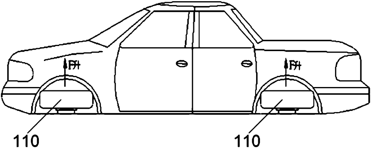
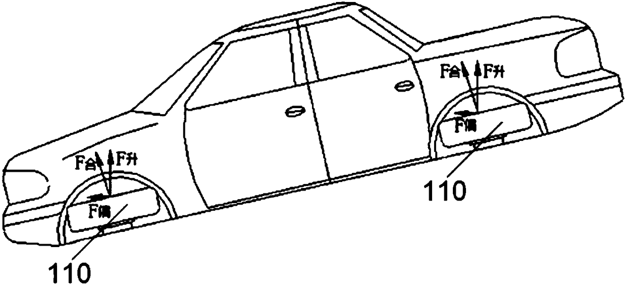
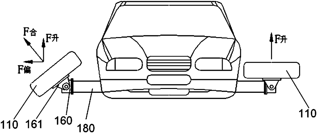
[0042] As shown in Figures 1 to 9, the present invention provides a wheel position conversion device for an electric vehicle. Four hydraulic lifts 190 in the front trunk 191 and the trunk 192.

[0043] As shown in Figures 1 to 4, the four integrated driving and steering wheels 110 are respectively installed at the left and right symmetrical positions of the front and rear ends of the body base, and the hub motor 140 of the overall driving device of the automobile is integrated inside the wheel to directly drive the wheel to rotate; in addition, the wheel Steering motor 163 and semi-active suspension 162 are also integrated in the car, and the car drives the wheel deflection through the steering-by-wire technology; image 3 As shown, four hydraulic lifting devices 190 are respectively installed at the front and rear of the vehicle body, which can lift and support the vehicle body. The lifting height is just enough to make the wheels leave the ground; space, the hydraulic cylin...

Embodiment 2

[0054] As shown in Figures 1 to 9, the present invention provides a wheel position conversion device for an electric vehicle, the main body of which includes an integrated driving and steering wheel 110, a wheel propeller 121, and a rotary telescopic hydraulic cylinder 180 responsible for wheel extension and rotation. And four hydraulic lifting devices 190 respectively fixed in the front trunk box 191 and the trunk box 192 of the vehicle body.

[0055] As shown in 1 to 4, the four integrated driving and steering wheels 110 are respectively installed at the left and right symmetrical positions of the front and rear ends of the body base, and the spokes 120 of the four integrated driving and steering wheels are all in the form of propellers. The hub motor 140 of the device is integrated inside the wheel, controlled by the hub motor controller 210, energizing the electromagnetic winding 141, and directly driving the wheel to rotate; in addition, the steering motor 163 and the semi...


PUM


Abstract

The invention discloses a wheel position changing device of an electric vehicle. The wheel position changing device comprises: an axle, a steering bracket, a motor base, a piston rod, a spring, a steering motor and a retractable hydraulic cylinder, wherein the axle penetrates through the center of a wheel hub motor and is fixed with a stator of the wheel hub motor; a wheel freely rotates relative to the axle; the steering bracket is fixedly connected with the axle or the steering bracket and the axle form a whole body; the steering bracket is provided with two parallel stretching-out legs; the motor base is arranged between the two stretching-out legs of the steering bracket and is provided with a containing space; the piston rod penetrates through the motor base and is fixed between the two stretching-out legs of the steering bracket; the spring is arranged between the motor base and the stretching-out legs of the steering bracket; the steering motor is arranged in the containing space and can drive the piston rod to rotate; the retractable hydraulic cylinder is arranged at the bottom of the vehicle and a piston rod of the retractable hydraulic cylinder is connected with the base and is used for enabling the integrated wheel to stretch out of a vehicle body. The invention further discloses a flying-driving electric vehicle.

Description

technical field [0001] The invention relates to the field of ground-air amphibious vehicles, in particular to an electric vehicle wheel position conversion device and a land-air dual-purpose electric vehicle. Background technique [0002] With the rapid development of modern social economy, cars are not only a means of transportation in daily life, but also a way of life for people. In recent years, the number of cars in cities has increased significantly, and traffic jams have become a daily phenomenon in most cities. Excessive traffic pressure will bring a series of problems and hidden dangers. How to effectively solve the traffic problems in modern cities has become urgent. [0003] Combined with the concept of flying cars proposed by Henry Ford, some people have proposed the idea of ​​relying on flying cars to relieve the pressure on ground traffic, which has also made flying cars a hot research topic in related industries around the world. It is not difficult to find ...

Claims


Application Information

Patent Timeline
Patent Type & Authority Patents(China)
IPC IPC(8): B60F5/02B60B19/00B64C27/32
CPCB60B19/00B60F5/02B64C27/32
Inventor 靳立强田端洋张志阳褚学聪
Owner JILIN UNIV
Learn More