
Blanking device and material conveying system

A blanking device and conveying system technology, which is applied to conveyors, conveyor objects, conveyor control devices, etc., can solve the problems of complex coal quality working conditions, high frequency of malfunction of coal blocking switches, detection of coal blocking switches triggering, etc.

Active Publication Date: 2018-12-14
CHINA SHENHUA ENERGY CO LTD +2
View PDF9 Cites 0 Cited by
  • Summary
  • Abstract
  • Description
  • Claims
  • Application Information

AI Technical Summary

Problems solved by technology

[0002] At present, in the process of coal material transportation, due to uncertain factors such as changes in the moisture content of raw coal and coal sticking in the coal drop tube of the conveying system, the conveying system usually has irregular material blockages, while the belt conveyor of the conveying system will be normal. This will lead to the aggravation of the coal blocking phenomenon at the coal blocking place and coal overflow, which will cause equipment damage to a certain extent, and then need to spend material and manpower to clean up, resulting in economic losses
[0003] Therefore, in order to ensure the stable and reliable operation of the coal handling system, a coal blocking detection switch is usually installed at the coal handling system where the coal is easy to block. The misoperation frequency of the coal switch is relatively high. For example, debris often entangles the probe of the coal blocking switch, resulting in the occurrence of misoperation triggered by the detection of coal blocking switch. Afterwards, personnel need to clean up the debris wrapped around the probe before continuing to operate.
In this way, this kind of detection coal blocking switch is greatly affected by coal quality and environmental factors, resulting in high malfunctions, high maintenance costs, and unable to make the coal handling system run stably and well.

Method used


Image

  • Blanking device and material conveying system

Examples


Embodiment Construction

[0021] Specific embodiments of the present invention will be described in detail below in conjunction with the accompanying drawings. It should be understood that the specific embodiments described here are only used to illustrate and explain the present invention, and are not intended to limit the present invention.

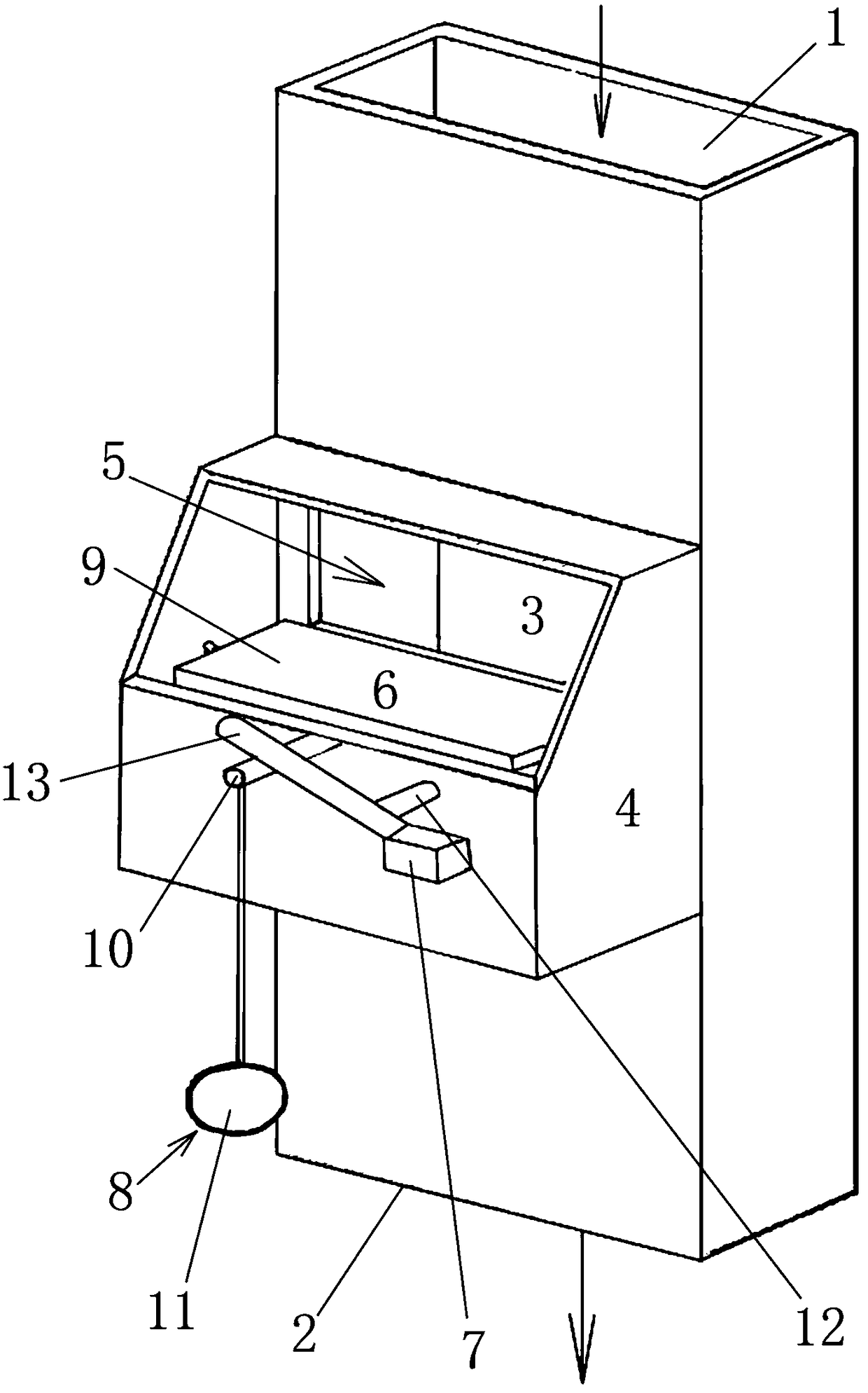
[0022] Such as figure 1 As shown, the blanking device of the present invention includes a overflow shell 4, a material receiving part 6 and a switch device 7 and a blanking channel 3 with a feed port 1 and a discharge port 2, for example, as figure 1 As shown, a blanking channel 3 is formed in the cuboid-shaped coal-falling tube, and a overflow shell 4 is arranged on the outer surface of the blanking channel 3, and the overflow shell 4 passes through the overflow port 5 on the wall of the blanking channel 3 Connected with the blanking channel 3, the overflow shell 4 is provided with a material receiving part 6 for receiving the overflow overflowed into the over...


PUM


Abstract

The invention relates to the field of material conveying and discloses a blanking device and a material conveying system. The blanking device comprises a blanking channel provided with a feeding hole and a discharging hole; the blanking device further comprises a material overflowing shell, a material accepting part and a switching device, wherein the material overflowing shell is arranged on the outer surface of the blanking channel; the material overflowing shell is communicated with the blanking channel through a material overflowing hole in a wall of the blanking channel; the material accepting part is arranged in the material overflowing shell and is used for receiving overflowed materials which are overflown into the material overflowing shell through the material overflowing hole; the material accepting part can move and drive the switching device to move when received overflowed materials reach a pre-set quantity, so that a material conveyor located at the upstream of the blanking device is out of work; and furthermore, the blanking device can be used for accurately and reliably detecting blocked materials and completely preventing incorrect actions, so that the materials can be stably and reliably conveyed.

Description

technical field [0001] The invention relates to the technical field of material conveying, in particular to a material conveying device capable of effectively preventing accidents caused by material blocking during material conveying, and a material conveying system with the material conveying device. Background technique [0002] At present, in the process of coal material transportation, due to uncertain factors such as changes in the moisture content of raw coal and coal sticking in the coal drop tube of the conveying system, the conveying system usually has irregular material blockages, while the belt conveyor of the conveying system will be normal. This will lead to the aggravation of the coal blocking phenomenon at the coal blocking place and coal overflow, which will cause equipment damage to a certain extent, and then need to spend material and manpower to clean up, resulting in economic losses. [0003] Therefore, in order to ensure the stable and reliable operation...

Claims


Application Information

Patent Timeline
Patent Type & Authority Patents(China)
IPC IPC(8): B65G43/08
CPCB65G43/08B65G2201/045
Inventor 杨晓平
Owner CHINA SHENHUA ENERGY CO LTD
Learn More