Grille energy-dissipation type flood discharge device

A grid and energy dissipation technology, applied in the field of spillway, can solve the problems of slope or bottom impact, large water impact potential energy, etc., achieve the effect of reasonable structure, ensure safe and stable operation, and avoid channel collapse accidents

Active Publication Date: 2016-08-17
SOUTHERN XINJIANG ELECTRICITY SUPPLY COMPANY OF STATE GRID XINJIANG ELECTRIC POWER +1
View PDF6 Cites 4 Cited by
  • Summary
  • Abstract
  • Description
  • Claims
  • Application Information

AI Technical Summary

Problems solved by technology

[0003] The invention provides a grid energy dissipation flood discharge device, which overcomes the deficiencies of the prior art above, and can effectively solve the problem that the impact potential energy of the water flow is relatively large, which may cause damage to the wall, side slope or bottom of the spillway at the bend of the spillway. shock problem

Method used


Image

  • Grille energy-dissipation type flood discharge device

Examples


Embodiment Construction

[0014] The present invention is not limited by the following examples, and specific implementation methods can be determined according to the technical solutions of the present invention and actual conditions.

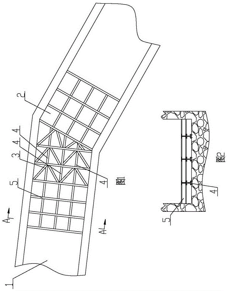
[0015] In the present invention, for the convenience of description, the description of the relative positional relationship of each component is based on the description attached to the description. figure 1 The layout method is described, such as: the positional relationship of top, bottom, left, right, etc. is based on the attached figure 1 determined by the layout direction.

[0016] Below in conjunction with embodiment and accompanying drawing, the present invention will be further described:

[0017] as attached figure 1 As shown, the grid energy dissipation flood discharge device includes a straight section flow channel 1 and a curved section flow channel 2; a grid assembly is fixed at the bottom of the curved section flow channel 2; the grid assembly includes...


PUM


Abstract

The invention relates to the technical field of flood discharge channels, and discloses a grille energy-dissipation type flood discharge device. The device comprises a straight section flow channel and a bending section flow channel; a grille assembly is fixed at the bottom of the bending section flow channel; the grille assembly comprises at least one energy-dissipation grille used for decreasing water flow impact potential energy and at least one flowguide grille guiding water flow to the middle of the flow channel; each energy-dissipation grille is a square grille which is in matrix distribution, each flowguide grille is in matrix distribution, and the triangle pointed-end points to the downstream flow channel. The grille energy-dissipation type flood discharge device is reasonable and compact in structure, and use is convenient; the energy-dissipation grilles and triangular grilles which are fixed in a crossed mode decrease the potential energy and change the water flow direction for the water flow in the bending section flow channel in the continuous water flow discharging process, and therefore the washing force of the water flow to the wall or side slope or bottom of the bending section flow channel is decreased, hydraulic facilities in a hydropower plant are protected against damage, it is guaranteed that the hydropower plant operates safely and stably, and the accident of channel collapse is avoided.

Description

technical field [0001] The invention relates to the technical field of spillways, and relates to a grid energy dissipation flood discharge device. Background technique [0002] The hydropower plant mainly relies on the hydraulic potential energy to drive the water turbine to rotate, and the water turbine drives the generator to rotate and cut the magnetic force line to generate electricity; however, when the hydropower plant suddenly loses pressure due to other external reasons, a large amount of flow cannot be discharged normally and needs to be discharged through the spillway ; For high-head hydropower stations, due to the influence of the terrain, the flow of the spillway is large, the drop is high, and the draft is deep, and the water flow will accumulate a lot of potential energy during flood discharge; The impact on the wall, slope or bottom of the spillway at the bend will pose a serious threat to the forebay dam or mountain of the hydropower plant, and there is a ris...

Claims


Application Information

Patent Timeline
Patent Type & Authority Applications(China)
IPC IPC(8): E02B8/06
CPCE02B8/06
Inventor 姚春风姚茹玲吾斯曼江杜奎张庚轩柴雪莉雍百炼姜军景天柱李斌
Owner SOUTHERN XINJIANG ELECTRICITY SUPPLY COMPANY OF STATE GRID XINJIANG ELECTRIC POWER
Why Eureka
Try Eureka