Safety handrail

A handrail and safety technology, applied in handrails, public buildings, building structures, etc., can solve problems such as loose handrails, many specifications, and reduce costs, and achieve the effects of preventing relative rotation, ensuring stability, and ensuring safety

Active Publication Date: 2016-08-17
CHONGQING QINGZHIDU BUILDING MATERIAL CO LTD
View PDF7 Cites 3 Cited by
  • Summary
  • Abstract
  • Description
  • Claims
  • Application Information

AI Technical Summary

Problems solved by technology

[0002] At present, the handrails used in bathrooms, swimming pools, aisles and other occasions are used to help old and young women and children get up and walk, so as to prevent accidents from falling. , its shortcomings are: the length cannot be extended or changed according to the site demand; the large number of specifications leads to heavy inventory and transportation burden
Patent No. CN201320194950 discloses a safety armrest, the armrest body includes a solid rod body and a protective shell covering the solid rod body, in order to prevent the protective shell from rotating relative to the solid rod body,

Method used


Image

  • Safety handrail
  • Safety handrail
  • Safety handrail

Examples


Embodiment 1

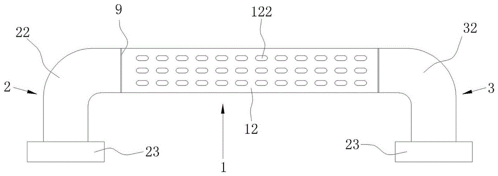
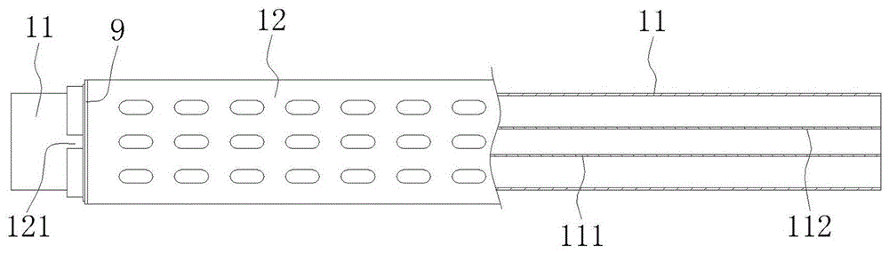
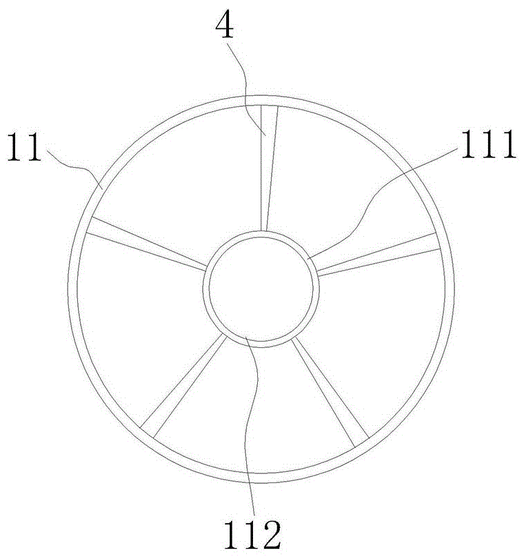
[0036] like figure 1As shown, a safety handrail includes a handrail tube 1, and the left and right ends of the handrail tube 1 are respectively fixed by a left mounting seat 2 and a right mounting seat 3. like figure 2 , image 3 As shown, the handrail tube 1 includes an inner tube 11 and a non-slip protective shell 12 covering the outer circumference of the inner tube 11. In order to achieve the purpose of anti-slip, the outer surface of the protective shell 12 can be provided with anti-skid patterns 122; There is a first connecting column 111 , a reinforcing rib 4 is connected between the outer circumference of the first connecting column 111 and the inner surface of the inner tube 11 , and the inner circumference of the first connecting column 111 has a first internal thread 112 .

[0037] Figure 4 The structure of the left mounting seat 2 is shown. The left mounting seat 2 includes a left fixing plate 21 and a left connecting pipe 22 engaged with the left end of the h...

Embodiment 2

[0043] Compared with the first embodiment, this embodiment mainly defines the matching and engaging structures of the left fixing plate 21 and the right fixing plate 31 and the protective cover 23 respectively. The matching structure of the left fixing plate 21 and the protective cover 23 is as follows: Figure 4 Shown: the left outer edge is provided with three concave notches 211, one side of the concave notches 211 is provided with a circumferentially extending extension 212, and a mounting opening 213 is left between the extension 212 and the other side , the upper end of the extension portion 212 is flush with the upper end of the recessed notch 211, and the thickness of the extension portion 212 is smaller than the thickness of the recessed notch 211. The inner side of the lower end of the protective cover 23 is provided with a protruding buckle 231 that matches the installation opening 213. The protruding buckle The size of the 231 can be entered from the installation op...

Embodiment 3

[0048] Compared with Embodiment 1, this embodiment is different in that the installation structures of the left threaded rod 222 and the right threaded rod 322 are defined. Generally speaking, taking the left threaded rod 222 as an example, such as Image 6 As shown in the figure, a relatively simple installation method between the left connecting pipe 22 and the inner pipe 11 is to set an internal thread in the fixing column 221. When installing, first screw one end of the left threaded rod 222 into the fixing column 221, and then screw the other end into the first A threaded connection is performed in the connecting column 111. The disadvantage of this installation method is that the connection of the left end of the inner pipe 11 needs to go through two threading processes, and the installation is not fast enough. , it will easily lead to the loss of parts due to the instability of the threaded connection, so it can be considered to fix the left threaded rod 222 in the fixi...


PUM


Abstract

The invention discloses a safety handrail. The safety handrail comprises a handrail tube and mounting bases arranged at the left end and the right end of the handrail tube. The handrail tube comprises an inner tube and a protecting case wrapping the inner tube. Each mounting base comprises a fixing disk and a connecting tube connected with the handrail tube. Each connecting tube is provided with a protecting cover in a penetrating mode, and the protecting cover is connected with the corresponding fixing disk in a clamped mode. The two ends of the inner tube are each internally provided with a connecting column with an internal thread. Reinforcing ribs are connected between the periphery of each fixing column and the inner surface of the corresponding connecting tube. A threaded rod extending out of the corresponding connecting tube is mounted in the fixing column of the connecting tube. The extension part of each threaded rod is provided with an external thread matched with the corresponding internal thread. The inner surface of the end of the left connecting tube is provided with an annular limiting flange which is provided with at least one boss extending in the radial direction. The outer diameter of the left end of the protecting case is matched with the inner diameter of the left connecting tube. The left end of the protecting case is provided with a clamping groove matched with the corresponding boss. The outer diameter of the protecting case is equal to the outer diameter of the left connecting tube and the outer diameter of the right connecting tube.

Description

technical field [0001] The invention belongs to the field of handrails, and in particular, is a safety handrail used in bathrooms, swimming pools, aisles and the like. Background technique [0002] At present, the handrails used in bathrooms, swimming pools, aisles and other occasions are used to assist the elderly, young, women and children to get up and walk, so as to prevent the occurrence of falling accidents. The existing safety handrails are only fixed with a fixed seat at each end of an iron pipe. , its shortcomings are: the length cannot be arbitrarily extended or changed according to the needs of the site; the large number of specifications leads to heavy inventory and transportation burdens. The patent document with the patent number of CN201320194950 discloses a safety handrail. The handrail body includes a solid rod body and a protective shell wrapped around the solid rod body. In order to prevent the protective shell from rotating relative to the solid rod body,...

Claims


Application Information

Patent Timeline
IPC IPC(8): E04F11/18E04H4/14
CPCE04F11/18E04F11/1802E04F11/1804E04F2011/1897E04H4/14
Inventor 杜玉见
Owner CHONGQING QINGZHIDU BUILDING MATERIAL CO LTD
Why Eureka
Try Eureka