Tunnel boring machine residue discharging device and trenchless tunnel boring machine provided with device

A tunnel boring machine and slag feeding technology, applied in tunnels, mining equipment, earthwork drilling and mining, etc., can solve problems such as complex structure of slag discharge system, impact on delivery projects, hard rock shutdown blasting, etc.

Active Publication Date: 2016-08-17
FOSHAN YICAI FIBERGLASS REINFORCED PLASTIC PROD
View PDF6 Cites 2 Cited by
  • Summary
  • Abstract
  • Description
  • Claims
  • Application Information

AI Technical Summary

Problems solved by technology

[0004] Existing non-excavation tunneling equipment usually uses large cutters with a diameter slightly larger than the cross-section for excavation, and most of them have soil bins. When the entire cutterhead is twisted, a huge driving torque and a huge thrust are required, making the entire excavation During the excavation process, there are defects such as high energy consumption and low excavation speed, and the adaptability to different geological conditions is limited. When encountering hard rocks during the excavation process, it is often necessary to stop blasting, which affects the delivery of the project
In addition, the existing trenchless tunneling equipment needs to increase the soil bin, resulting in a complex structure of the overall slag discharge system and low conveying speed, which cannot be adapted to high-speed trenchless tunneling equipment

Method used


Image

  • Tunnel boring machine residue discharging device and trenchless tunnel boring machine provided with device
  • Tunnel boring machine residue discharging device and trenchless tunnel boring machine provided with device
  • Tunnel boring machine residue discharging device and trenchless tunnel boring machine provided with device

Examples


Embodiment Construction

[0020] Embodiments of the present invention are described in detail below, examples of which are shown in the drawings, wherein the same or similar reference numerals designate the same or similar elements or elements having the same or similar functions throughout. The embodiments described below by referring to the figures are exemplary only for explaining the present invention and should not be construed as limiting the present invention.

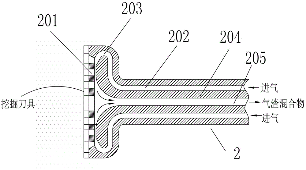
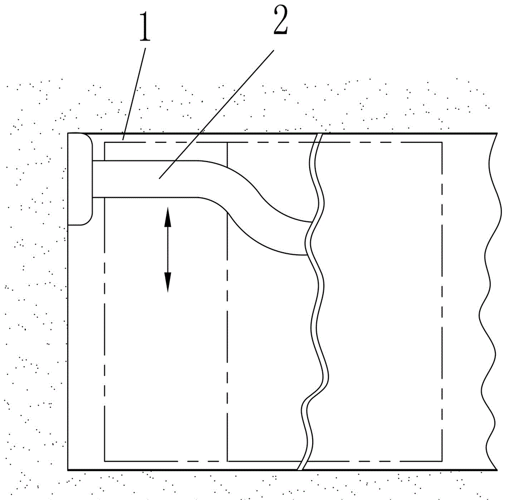
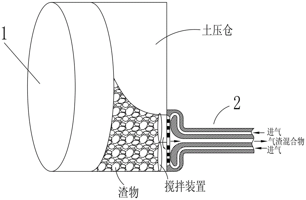
[0021] Such as figure 1 As shown, a slag discharge device for a tunnel boring machine described in the present invention includes a slag discharge pipe body 2 for installing an excavating tool at the front, realizing the integrated structure of the excavating tool and the slag discharge pipe body 2 . The front part of the slag discharge pipe body 2 is provided with a slag inlet hole 201, and the slag discharge pipe body 2 is provided with a shroud 204, and the inner lumen and the outer surface of the shroud 204 are airtightly isolated fr...


PUM


Abstract

The invention relates to a tunnel boring machine residue discharging device, which comprises a residue discharging pipe body, wherein the front part of the residue discharging pipe body is provided with residue inlet holes; a flow guide cover is arranged in the residue discharging pipe body; the inner pipe cavity of the flow guide cover is in airtight isolation from the outer surface of the flow guide cover; the outer surface of the flow guide cover and the inner surface of the flow guide cover form a compressed air inlet passage into which compressed air is input from the outside; the inner pipe cavity of the flow guide cover is a residue discharging air passage; the compressed air inlet passage communicates with the residue discharging air passage through the front port of the flow guide cover; airflow inputted into the compressed air inlet passage from the outside passes through the front end of the flow guide cover and then enters the residue discharging air passage; the residue inlet holes form a negative pressure area; and residues from the outside enter the front port of the flow guide cover through the residue inlet holes and are then discharged from the residue discharging air passage after being mixed with the compressed air. Meanwhile, the invention further discloses a trenchless tunnel boring machine provided with the device. Related structures such as soil warehouses can be omitted, and as soil warehouses are unnecessary to be configured, a residue discharging system of an existing trenchless tunnel boring machine is simplified.

Description

technical field [0001] The invention specifically relates to a tunnel boring machine slag discharge device and a trenchless tunnel boring machine. Background technique [0002] Tunnel boring machine is the main equipment for trenchless tunnel construction. Its excavation method is: use a large cutter head with a diameter slightly larger than the outer diameter of the machine to rotate and excavate. The large cutter head is evenly distributed with multiple excavating knives to "eat soil" synchronously. The soil bin is transported out to the surface by conveying machinery. The technical features of this traditional method are multiple cutters on the same plane, synchronous rotary excavation, powerful jacking, powerful rotation, soil bin balance, and soil transportation. [0003] Tunnel boring machine is an advanced technical equipment with high speed, good quality and high safety performance in urban subway construction and pipe gallery construction. The interval tunnel const...

Claims


Application Information

Patent Timeline
IPC IPC(8): E21D9/13E21D9/10
CPCE21D9/10E21D9/13
Inventor 梁定辉梁军梁慧妍
Owner FOSHAN YICAI FIBERGLASS REINFORCED PLASTIC PROD
Why Eureka
Try Eureka