Continuous deslagging device of fluidized bed gasification furnace and deslagging method of continuous deslagging device

A fluidized bed gasification furnace, gasification furnace technology, applied in the mechanical details of the gasification device, granular/powdered fuel gasification, combustible gas production, etc., can solve the problem of large water consumption, low efficiency of slag removal, and difficult operation and other problems, to achieve the effect of reducing slagging cost, improving slagging efficiency, and simplifying slagging process

Pending Publication Date: 2021-01-19
XINNENG ENERGY CO LTD
View PDF0 Cites 0 Cited by
  • Summary
  • Abstract
  • Description
  • Claims
  • Application Information

AI Technical Summary

Problems solved by technology

The biggest disadvantage of the dry slagging system is that it is very difficult to operate, and the central air pipe is severely worn, which may even cause leakage, causing overheating and slagging inside the lower slag channel of the gasifier, and poor system operation stability; moreover, the dry slagging The slag discharge temperature is high, the temperature resistance requirements for the slag discharge valve are high, the slag discharge pipe is easy to wear and leak, and because the pressure relief gas carries a large amount of dust and steam, the site is seriously polluted
[0003] Wet slag discharge is that the ash is discharged from the slag discharge pipe at the bottom of the gasifier to the slag receiving tank and the pressure transformer slag tank and cooled by quenching water. Although the temperature of the slag discharge system is low and the environmental pollution is small, it is difficult to accurately Controlling the amount of slag discharge makes it difficult to control the slag discharge of the gasifier; and this slag discharge method needs to continuously feed chilled water, and the discharge of slag water is large, which leads to large water consumption, and the various processes of the slag discharge system Pipelines are easily blocked, resulting in unstable production
[0004] In addition, the traditional dry slagging and wet slagging both need to use intermittent slagging, and the high-pressure ash needs to be discharged after continuous depressurization. The system is complicated, the slagging process is cumbersome, and the slagging efficiency is low.

Method used


Image

  • Continuous deslagging device of fluidized bed gasification furnace and deslagging method of continuous deslagging device
  • Continuous deslagging device of fluidized bed gasification furnace and deslagging method of continuous deslagging device

Examples


Embodiment 1

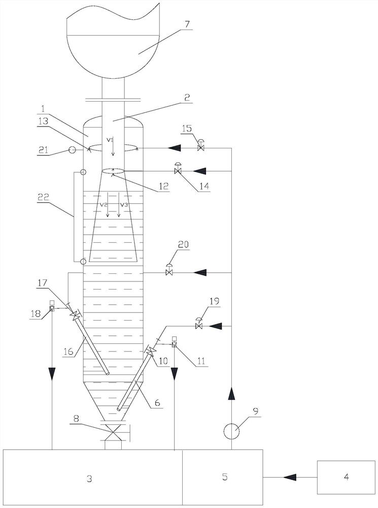
[0029] Embodiment 1: as Figure 1-2 As shown, a continuous slagging device for a fluidized bed gasifier 7 includes a slagging tank 1, a slag lowering channel 2, a slag pool 3, a water source 4, a clean water pool 5 and a first slagging pipe 6; The top of the slag tank 1 is fixed with a lower slag channel 2, and the top of the lower slag channel 2 communicates with the slag outlet of the gasifier 7; connected; the pipeline between the slag tank 1 and the slag pool 3 is provided with a drain valve 8; the overflow port of the slag pool 3 and the water source 4 are all connected with the water inlet of the clean water pool 5; the water outlet of the clean water pool 5 is connected with the The water inlet of the circulation pump 9 is connected, and the water outlet of the circulation pump 9 is connected with the water inlet of the slag discharge tank 1; the first slag discharge pipe 6 is fixed on the side wall below the slag discharge tank 1 obliquely; The slag inlet end of 6 is ...

Embodiment 2

[0036] Embodiment 2: utilize the slagging method of embodiment 1 slagging device, it comprises the following steps:

[0037] (1) The ash falls from the lower slag channel 2 to the surface of the solution and forms a scum layer. At the same time, the inner spray head 12 in the lower slag channel 2 sprays water, and the spray water carries the scum layer to settle rapidly, so that the ash and slag Settled to below the slagging tank 1;

[0038] (2) Open the first quick-opening valve 10 and the first decompression angle valve 11, and the ash solution in the bottom of the slag discharge tank 1 is squeezed from the first slag discharge pipe 6 into the slag pool 3 under the action of pressure; The ash and slag solution at the bottom of the slag discharge tank 1 passes through the first slag discharge pipe 6 to continuously reduce the pressure, and is discharged from high pressure to low pressure into the slag pool 3, which simplifies the slag discharge process and improves the slag d...


PUM


Abstract

The invention discloses a continuous deslagging device of a fluidized bed gasification furnace and a deslagging method of the continuous deslagging device. The deslagging device comprises a deslaggingtank, a slag discharge channel, a slag pool, a water source, a clean water pool and a first deslagging pipe; a first deslagging pipe is obliquely fixed on the side wall below the deslagging tank in apenetrating manner; the slag inlet end of the first deslagging pipe is positioned at the bottom in the deslagging tank, and the slag outlet end of the first deslagging pipe is communicated with a slag inlet of the slag pool through a pipeline. The method comprises the following steps: (1) settling ash slag to a position below the deslagging tank; and (2) extruding the ash slag solution into the slag pool from the first deslagging pipe. The deslagging device and the deslagging method thereof has the beneficial effects that the deslagging device is simple in structure and easy to implement; thedeslagging system is simplified, so that the investment of equipment is reduced, and the deslagging cost is reduced; the deslagging process is simplified, and the deslagging efficiency is improved; the deslagging amount of the gasification furnace can be accurately controlled; reutilization of water resources is achieved, and waste of the water resources is avoided.

Description

Technical field: [0001] The patent of the invention belongs to the technical field of slagging of fluidized bed gasification furnace, and specifically relates to a continuous slagging device and a slagging method of a fluidized bed gasification furnace. Background technique: [0002] Common slagging methods for fluidized bed gasifiers currently include fixed bed dry slagging method and wet slagging method; the slagging systems of the above two methods include slag receiving tanks (or high-pressure slag tank), variable pressure slag tank and low pressure slag tank. Among them, the dry slag discharge method is to install a central air pipe in the slag receiving tank, and the central air pipe extends into the slag channel of the gasifier, and adopts air control to discharge slag, that is, by controlling the gas volume in the slag channel of the gasifier, To control the slag rate. The biggest disadvantage of the dry slagging system is that it is very difficult to operate, and ...

Claims


Application Information

Patent Timeline
Patent Type & Authority Applications(China)
IPC IPC(8): C10J3/56C10J3/54C10J3/72
CPCC10J3/54C10J3/56C10J3/72C10J2200/09
Inventor 刘海建张晓阳李美喜武恒吴松怡马万里霍学斌王正
Owner XINNENG ENERGY CO LTD
Why Eureka
Try Eureka