
Damping device and method for beam-array-shaped periodical piezoelectric composite structure

A vibration damping device and piezoelectric composite technology, which is applied to piezoelectric effect/electrostrictive or magnetostrictive motors, electrical components, vibration suppression adjustments, etc., can solve problems such as vibration reduction and isolation in low-frequency ranges that cannot be achieved , to achieve the effect of eliminating algorithm design and high reliability

Inactive Publication Date: 2016-08-17
HUAZHONG UNIV OF SCI & TECH
View PDF5 Cites 14 Cited by
  • Summary
  • Abstract
  • Description
  • Claims
  • Application Information

AI Technical Summary

Problems solved by technology

However, the forbidden band of phononic crystals often appears in the high-order frequency band, and vibration reduction and vibration isolation in the low-frequency range cannot be achieved.

Method used

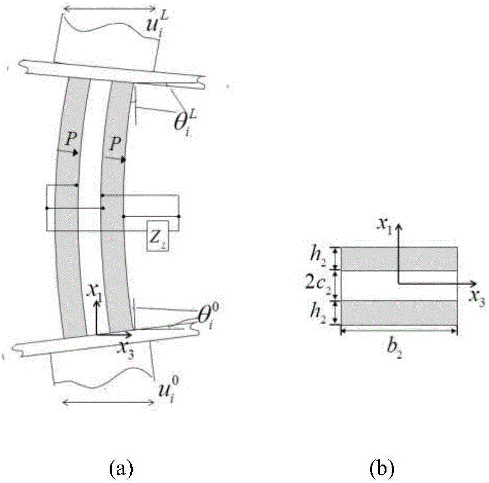
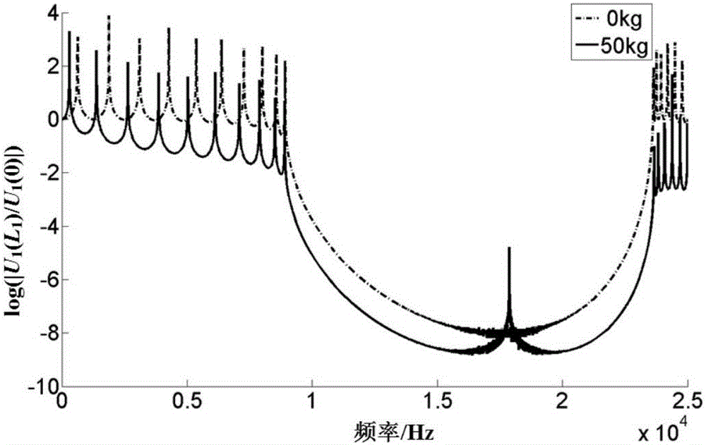

Image

  • Damping device and method for beam-array-shaped periodical piezoelectric composite structure
  • Damping device and method for beam-array-shaped periodical piezoelectric composite structure
  • Damping device and method for beam-array-shaped periodical piezoelectric composite structure

Examples


Embodiment Construction

[0029] In order to make the object, technical solution and advantages of the present invention clearer, the present invention will be further described in detail below in conjunction with the accompanying drawings and preferred embodiments. It should be understood that the specific embodiments described here are only used to explain the present invention, not to limit the present invention. In addition, the technical features involved in the various embodiments of the present invention described below can be combined with each other as long as they do not constitute a conflict with each other.

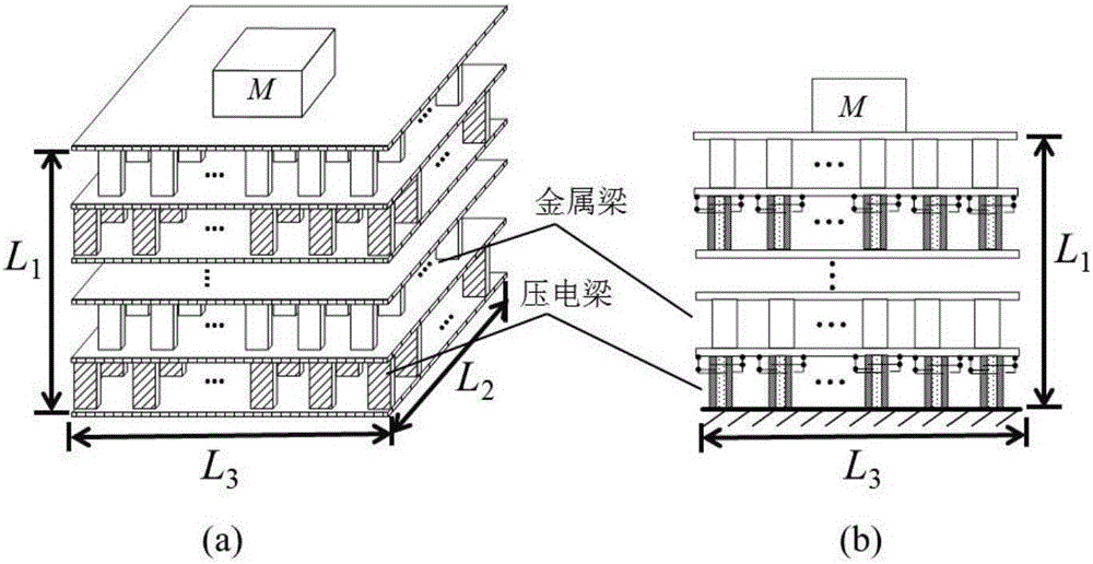
[0030] figure 1 It shows a three-dimensional schematic diagram and a two-dimensional schematic diagram of a preferred embodiment of the vibration damping device of the present invention. The overall structure is formed by alternately stacking multilayer metal beam arrays and multilayer piezoelectric bicrystalline beam arrays. board separated. The ends of each beam are fixed to the in...


PUM


Abstract

The invention discloses a damping device for a beam-array-shaped periodical piezoelectric composite structure. According to the structure of the damping device, multiple layers of piezoelectric beam arrays and multiple layers of metal beam arrays are alternately stacked; the adjacent layers are fixedly connected through insulating plates; and all piezoelectric beams are connected with shunt circuits to form loops, wherein each shunt circuit is formed in a manner that an inductor and a resistor are connected in series. The invention further provides a damping optimizing method based on the above device, the resistance value is gradually increased from zero, and meanwhile the inductance value is determined according to circuit parallel resonance conditions. The attenuation effect of vibration is gradually enhanced along with increasing of the resistance, the frequency response curve of the damping device is overall lowered along with increasing of the resistance, and parameters of the shunt circuits become the optimal tuning parameters till the frequency response curve peak of the damping device becomes the minimum. By means of the device and the method, an isolation effect is achieved on excitation in the horizontal direction / perpendicular direction due to frequency forbidden band characteristics, low-frequency excitation in the transverse x3- direction can be adjusted in real time through the shunt circuits, and therefore the vibration inhibiting function is achieved.

Description

technical field [0001] The invention relates to the field of precision machining platform vibration reduction technology, in particular to a beam array-shaped periodic piezoelectric composite structure vibration reduction device and a vibration reduction method. Background technique [0002] Ultra-precision machining platforms are very sensitive to external disturbances, and small disturbances in the environment will seriously affect their positioning accuracy. Therefore, vibration damping devices are required to reduce the impact of external environmental disturbances. The disturbance in the external environment usually has the characteristics of low frequency, wide frequency band and complex source, so the vibration reduction system is required to have multi-directional vibration reduction function and broadband performance. [0003] Commonly used vibration reduction devices can be divided into two categories: passive vibration reduction and active vibration reduction. Pa...

Claims


Application Information

Patent Timeline
IPC IPC(8): F16F15/00F16F15/02H02N2/00
CPCF16F15/002F16F15/007F16F15/02H02N2/003
Inventor 胡元太王羽茜
Owner HUAZHONG UNIV OF SCI & TECH
Learn More