Masonry Bracket Unit

A bracket device and masonry technology, applied in furnaces, lighting and heating equipment, furnace components, etc., can solve the problems of large heat loss in the furnace, easy deformation, and cracks in the masonry, and achieve slow heat transfer speed and heat. The effect of slow transfer and reduced heat loss

Active Publication Date: 2017-12-08
HUATIAN ENG & TECH CORP MCC +1
View PDF8 Cites 0 Cited by
  • Summary
  • Abstract
  • Description
  • Claims
  • Application Information

AI Technical Summary

Problems solved by technology

Conventional masonry brackets are usually welded by steel plates, which are often accompanied by the following technical problems during use: 1) The brackets are welded by steel plates, and then directly welded with masonry steel plates, because the masonry bracket plates are directly Welded on the masonry steel plate, the heat loss in the kiln is large, and the bracket is prone to deformation after being heated at high temperature; The pouring material around the bracket is heated and expanded, and the bracket cannot expand and move synchronously with the pouring material, resulting in cracks and collapse of the masonry

Method used


Image

  • Masonry Bracket Unit
  • Masonry Bracket Unit
  • Masonry Bracket Unit

Examples


Embodiment 1

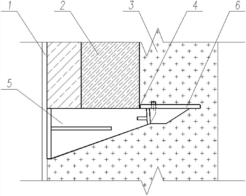
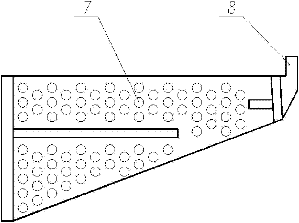
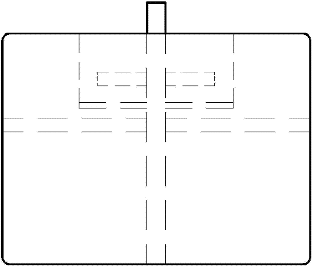
[0023] Such as Figure 1-6 As shown, the masonry bracket device of this embodiment includes a bracket 5 and a tray 6; wherein, the bracket 5 includes front and rear vertical plates arranged in parallel and at intervals, and two ends are connected with the front and rear vertical plates respectively. The connected connecting plate, the front of the front vertical plate is provided with a cylindrical boss 8; the tray 6 includes a horizontal supporting plate 4, a vertical stiffener 10 vertically arranged with the horizontal supporting plate 4, and a The circular hole 9;

[0024] When the boss is inserted into the circular hole 9, the rear side of the vertical stiffener 10 is attached to the front side of the front end plate.

[0025] The rear vertical plate and the masonry steel plate 1 are welded together, and the refractory brick 2 is built between the horizontal supporting plate 4 and the masonry steel plate 1, and the bracket 5, the tray 6 and the refractory brick 2 are cast...

Embodiment 2

[0029] On the basis of the above embodiment, the vertical length of the front vertical board is smaller than the vertical length of the rear vertical board, the connecting board is arranged in the vertical plane, and the connecting board The shape is trapezoidal.

[0030] Since in the stress system of this embodiment, whether the moment change or the shear force change along the horizontal direction on the connecting plate decreases gradually from the rear side to the front side, the shape of the connecting plate is set in this embodiment It is trapezoidal, and the vertical length of the front vertical board is smaller than the vertical length of the rear vertical board. This design not only ensures the strength of the masonry bracket of this embodiment, but also saves materials and reduces the weight of the masonry bracket.

Embodiment 3

[0032] On the basis of the above-mentioned embodiment, a bracket stiffening plate is arranged between the front and rear vertical plates and the connecting plate, and the bracket 5 stiffening plate is perpendicular to the front and rear vertical plates and the The connecting plate, the stiffening plate of the bracket 5 is a triangular plate.

[0033] A stiffening plate is arranged between the front and rear vertical plates and the connecting plate, which can enhance the rigidity of the bracket 5 to both sides, and when the bracket is subjected to forces on the left and right sides, no plastic deformation will occur, avoiding the impact caused by the casting material. 3 extrusion and deformation. If the bracket is deformed, the support capacity for the heat-resistant bricks and castables above will be reduced, so it is necessary to avoid plastic deformation of the bracket.


PUM


Abstract

The invention discloses a masonry bracket device, and mainly aims at the problem that the masonry bracket device in the prior art cannot move with the pouring material, and proposes a masonry bracket device, including a bracket and a tray; wherein, the The bracket includes front and rear vertical plates arranged in parallel intervals, connecting plates connected to the front and rear vertical plates at both ends, and a cylindrical boss is arranged in front of the front vertical plate; the tray includes a horizontal supporting plate , a vertical stiffening plate vertically arranged on the lower surface of the horizontal supporting plate and a round hole adapted to the boss; when the boss penetrates the round hole, the rear of the vertical stiffening plate The side is attached to the front side of the front panel. The tray of the present invention can move with the expansion of the pouring material without causing cracks in the pouring material. The invention is easy to install, and the heat loss in the kiln is small.

Description

technical field [0001] The invention relates to a masonry supporting device structure for an industrial furnace, in particular to a masonry bracket device. Background technique [0002] In recent years, with the rapid development of national infrastructure, industrial furnaces, as key equipment for industrial heating, have been well developed in terms of scale, type and quantity, and are widely used in metallurgy, chemical industry, cement and other industries. Economic development has made great contributions; however, my country's industrial furnaces are far behind the international advanced level in terms of operation level, safety performance and energy consumption. At the same time, it also means that our country has great potential in the field of industrial furnace energy saving and technology improvement. How to reduce the energy consumption of industrial furnaces, improve the safety performance of installation and use, and optimize the operation mode is the current s...

Claims


Application Information

Patent Timeline
Patent Type & Authority Patents(China)
IPC IPC(8): F27D1/00
CPCF27D1/00
Inventor 王浩詹茂华戴红周炜
Owner HUATIAN ENG & TECH CORP MCC
Why Eureka
Try Eureka