
Water cooling device

A water-cooling device and water-cooling jacket technology, which is applied in the field of heating furnaces, can solve the problems of shortening the life of the oil-cooling jacket sealing ring, complicated structure of the oil-cooling device, affecting the service life of bearings, etc., so as to achieve high production costs, save time and labor costs, and improve The effect of equipment life

Inactive Publication Date: 2016-08-17
YANCHENG FENGDONG SPECIAL FURNACE IND
View PDF6 Cites 2 Cited by
  • Summary
  • Abstract
  • Description
  • Claims
  • Application Information

AI Technical Summary

Problems solved by technology

[0002] In the prior art, it is common to use an oil cooling device to cool the stirring fan bearing of the heating furnace, but the oil cooling device has a complicated structure, resulting in high cost
At the same time, the oil is volatile, which will make the appearance of the equipment environment poor, and it needs to be wiped manually, which is time-consuming and laborious
In addition, the consumption of heat transfer oil is high and the price is high, which increases the production cost, and because of the high boiling point of the oil, the cooling effect is mediocre, which will shorten the life of the sealing ring inside the oil cooling sleeve, and at the same time affect the service life of the bearing installed on the shaft seat

Method used


Image

  • Water cooling device
  • Water cooling device
  • Water cooling device

Examples


Embodiment Construction

[0017] In order to further illustrate the technical means adopted by the present invention and the technical effects achieved, the following will be described in detail in conjunction with the accompanying drawings and embodiments.

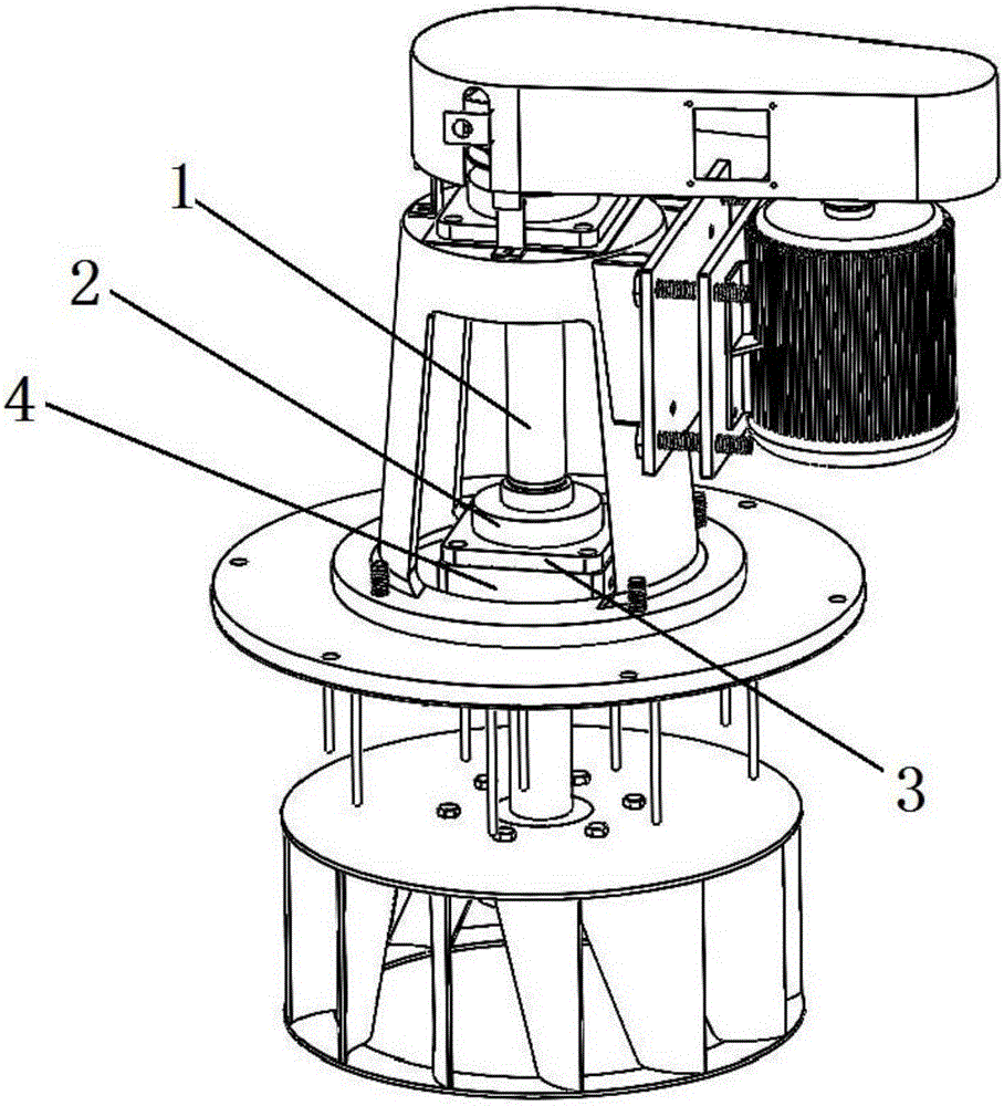
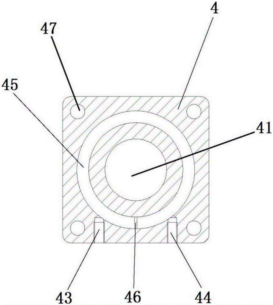
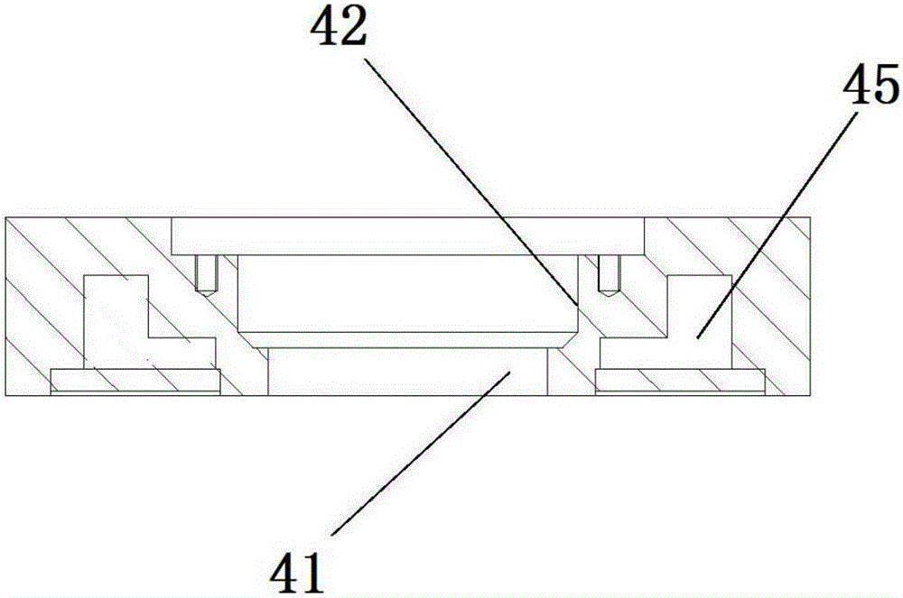
[0018] refer to Figure 1 to Figure 3 , The water cooling device of the present invention includes a stirring shaft 1 , a stirring bearing 2 sleeved on the stirring shaft 1 , a bearing seat 3 , and a water cooling jacket 4 . The water cooling jacket 4 is arranged below the bearing seat 3 , and the center of the water cooling jacket 4 is provided with a circular connection hole 41 , and a sealing step 42 is provided above the connection hole 41 , and the water cooling jacket 4 is sleeved on the stirring shaft 1 through the connection hole 41 . A water inlet 43 and a water outlet 44 are arranged on the side wall of the water cooling jacket 4 , and the water inlet 43 and the water outlet 44 are arranged on the same side of the water cooling jacket 4 ...


PUM


Abstract

The invention provides a water cooling device, which includes a stirring shaft, a stirring bearing sleeved on the stirring shaft, a bearing seat, and a water cooling jacket. The water-cooling sleeve is set under the bearing seat, a circular connection hole is provided in the center of the water-cooling sleeve, and a sealing step is provided above the connection hole, and the water-cooling sleeve is sleeved on the On the stirring shaft, a water inlet and a water outlet are arranged on the side wall of the water cooling jacket, and an annular connecting channel is arranged between the water inlet and the water outlet. The invention has the advantages of simple structure, ingenious design, good cooling effect, less manual maintenance, low production cost, long service life and the like.

Description

technical field [0001] The invention belongs to the field of heating furnaces, in particular to a water cooling device. Background technique [0002] In the prior art, it is common to use an oil cooling device to cool the bearing of the stirring fan of the heating furnace, but the oil cooling device has a complicated structure, resulting in high cost. At the same time, the oil is volatile, which will make the appearance of the equipment environment poor, and it needs to be manually wiped continuously, which is time-consuming and laborious. In addition, the consumption of heat transfer oil is high and the price is high, which increases the production cost, and because of the high boiling point of the oil, the cooling effect is average, which will shorten the life of the sealing ring inside the oil cooling sleeve, and affect the service life of the bearing installed on the shaft seat. Contents of the invention [0003] The purpose of the present invention is to provide a wa...

Claims


Application Information

Patent Timeline
Patent Type & Authority Applications(China)
IPC IPC(8): F27D9/00
CPCF27D9/00F27D2009/0013
Inventor 王群华李湧韩志春
Owner YANCHENG FENGDONG SPECIAL FURNACE IND
Learn More