Mechanical part hole pitch tolerance measuring test tool convenient to use

A technology of mechanical parts and hole spacing, which is applied in the field of mechanical parts inspection tools, can solve the problems of inability to adjust the distance between detection columns and inconvenient use, and achieve the effects of improving production efficiency and production quality, and being convenient to operate and use

Inactive Publication Date: 2016-08-17
CHANGZHOU JINHAILONG MACHINE MFG
7 Cites 1 Cited by

AI-Extracted Technical Summary

Problems solved by technology

[0003] A hole distance tolerance measuring tool for mechanical parts disclosed in the Chinese Invention Patent Application Publication No. CN203116673U is characterized in that it includes a positioning plate, and the two ends of the positioning plate are provided with a detection device with the same spacing as the distance between the two holes of the workpiece to be measured. column, and a handle is set in the midd...

Abstract

The invention discloses a mechanical part hole pitch tolerance measuring test tool convenient to use. The mechanical part hole pitch tolerance measuring test tool comprises a positioning plate. A sliding groove is formed in the upper surface of the positioning plate. A sliding block is arranged inside the sliding groove. A brake switch is arranged on the sliding block. One end of the brake switch extends into a strip-shaped through hole formed in the front face of the positioning plate. A dial gauge is arranged on the lower side of the strip-shaped through hole. A sliding detection column is arranged on the sliding block. A fixed detection column is arranged on one side of the sliding groove. A handle is arranged in the middle of the lower surface of the positioning plate. The mechanical part hole pitch tolerance measuring test tool convenient to use is convenient to operate, high in measuring efficiency, good in adaptability to the distance between two holes in various to-be-detected components, and capable of conveniently detecting whether the tolerance of holes in various to-be-detected components is qualified or not, workers can complete overall self-inspection at any time, and the production efficiency and the production quality are improved.

Application Domain

Slide gauges

Technology Topic

EngineeringProduction quality

Image

  • Mechanical part hole pitch tolerance measuring test tool convenient to use
  • Mechanical part hole pitch tolerance measuring test tool convenient to use
  • Mechanical part hole pitch tolerance measuring test tool convenient to use

Examples

  • Experimental program(1)

Example Embodiment

[0014] The technical solutions in the embodiments of the present invention will be clearly and completely described below with reference to the accompanying drawings in the embodiments of the present invention. Obviously, the described embodiments are only a part of the embodiments of the present invention, but not all of the embodiments. Based on the embodiments of the present invention, all other embodiments obtained by those of ordinary skill in the art without creative efforts shall fall within the protection scope of the present invention.
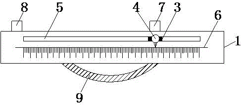
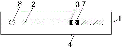
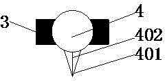
[0015] see Figure 1-3 , the present invention provides a technical solution: an easy-to-use measuring tool for measuring the hole distance tolerance of mechanical parts, comprising a positioning plate 1, the upper surface of the positioning plate 1 is provided with a chute 2, and the interior of the chute 2 is provided with a slider 3. The slider 3 is provided with a brake switch 4, one end of the brake switch 4 extends into the bar-shaped through hole 5 provided on the front of the positioning plate 1, and the lower side of the bar-shaped through hole 5 is provided with a scale 6 , the brake switch 4 is circular, and the bottom of the brake switch 4 is provided with a fingertip 401, the fingertip 401 is triangular, and the fingertip 401 is provided with a contrast line 402, the contrast line 402 and the scale 6 The tick marks are vertically parallel to each other.
[0016] The sliding block 3 is provided with a sliding detection column 7, one side of the chute 2 is provided with a fixed detection column 8, and a handle 9 is provided in the middle of the lower surface of the positioning plate 1, the handle 9 is arc-shaped, and the outer surface of the handle 9 is provided With non-slip threads.
[0017] When using this inspection tool for detection, the sliding detection column 7 slides on the chute 2 through the slider 3, so as to adjust the distance between the sliding detection column 7 and the fixed detection column 8, and put the brake switch 4 on the fingertip 401. The comparison line 402 is aligned with the specified scale line on the scale table 6, and the length value of the specified scale line is the same as the distance between the two holes of the workpiece to be tested, and then the sliding detection column 7 is fixed by the brake switch 4, and then the sliding detection column 7 is fixed. The center of the column 7 and the fixed detection column 8 are aligned with the center of the two holes of the workpiece and inserted into the two holes of the workpiece to be tested at the same time. If they cannot be inserted, it means that the hole distance and position are unqualified. Qualified, the inspector can hold the handle 9 provided in the middle of the lower surface of the inspection tool positioning plate 1 for inspection. The operation is convenient, the measurement efficiency is high, and the distance between the two holes of various parts to be inspected is well adapted. It can easily detect whether the tolerances of various parts to be inspected are qualified, and workers can self-inspect all of them at any time, which improves production efficiency and production quality. The operation is simple and convenient, and each piece can be inspected to improve production Efficiency and quality, the inspection column should be regularly inspected for tolerances, and those that reach the wear limit should be eliminated in time to prevent inspection errors.
[0018] Although embodiments of the present invention have been shown and described, it will be understood by those skilled in the art that various changes, modifications, and substitutions can be made in these embodiments without departing from the principle and spirit of the invention and modifications, the scope of the invention is defined by the appended claims and their equivalents.

PUM

no PUM

Description & Claims & Application Information

We can also present the details of the Description, Claims and Application information to help users get a comprehensive understanding of the technical details of the patent, such as background art, summary of invention, brief description of drawings, description of embodiments, and other original content. On the other hand, users can also determine the specific scope of protection of the technology through the list of claims; as well as understand the changes in the life cycle of the technology with the presentation of the patent timeline. Login to view more.

Similar technology patents

Household appliance control method and device and mobile terminal

InactiveCN103605531Aeasy to operateeasy to use
Owner:GD MIDEA AIR-CONDITIONING EQUIP CO LTD +1

Multi-stage oral-fluid testing device

ActiveUS20160121322A1easy to use
Owner:PREMIER BIOTECH LLC

System and method of monitoring temperature

InactiveUS7140768B2less susceptible to tampereasy to use
Owner:COLD CHAIN TECH

Classification and recommendation of technical efficacy words

  • easy to operate
  • easy to use

Lancet device

InactiveUS7303573B2inexpensively mass-producedeasy to operate
Owner:ABBOTT DIABETES CARE INC

Rapid and non-invasive optical detection of internal bleeding

InactiveUS20050065436A1easy to operaterapid and accurate result
Owner:HO WINSTON ZONH +2
Why Eureka
Try Eureka