Environmental noise suppression method and equipment

A technology of environmental noise and equipment, applied in the field of weak magnetic detection, can solve the problems of high complexity and inability to obtain the first-order gradient, and achieve the effect of simplifying the detection structure and improving the noise suppression performance

Active Publication Date: 2016-08-17
上海理微医疗科技发展有限公司
6 Cites 5 Cited by

AI-Extracted Technical Summary

Problems solved by technology

[0007] In view of the above-mentioned shortcomings of the prior art, the purpose of the present invention is to provide an environmental noise suppression method and equipment...

Method used

In summary, the environmental noise suppression method and equipment of the present invention need not increase the first-order gradient reference amount separately, adopt the correlation characteristics between the preparation techniques, and carry out gradient synthesis on two dimensions, thereby greatly improving The noise suppression performance of the gradiometer simplifies the system detection structure. Therefore, the present invention effectively overcomes various shortcomings in the prior art and has high industrial ap...

Abstract

The present invention provides an environmental noise suppression method and equipment. The environmental noise suppression equipment comprises a detection gradient component, a reference gradient component, a superconducting quantum interference device triaxial magnetometer component, and a readout circuit. The environmental noise suppression method comprises a step of collecting a first gradient output signal from the detection gradient component and a second gradient output signal from the reference gradient component, a step of using the superconducting quantum interference device triaxial magnetometer component to compensate the detection gradient component and the reference gradient component, and a step of allowing the first gradient output signal and the second gradient output signal to mutually compensate so as to synthesize a two-dimensional gradient to suppress environmental noise. According to the invention, the single adding of a gradient reference amount is not needed, by using the associated characteristic between preparation process, the gradient synthesis is carried out in the two-dimensional gradient, thus the noise suppression performance of a gradiometer is greatly improved, and a system detection structure is simplified.

Application Domain

Magnetic field measurement using superconductive devicesMagnetic measurement environmental aspects

Technology Topic

PhysicsEnvironmental noise +4

Image

  • Environmental noise suppression method and equipment
  • Environmental noise suppression method and equipment
  • Environmental noise suppression method and equipment

Examples

  • Experimental program(2)

Example Embodiment

[0041] Example one
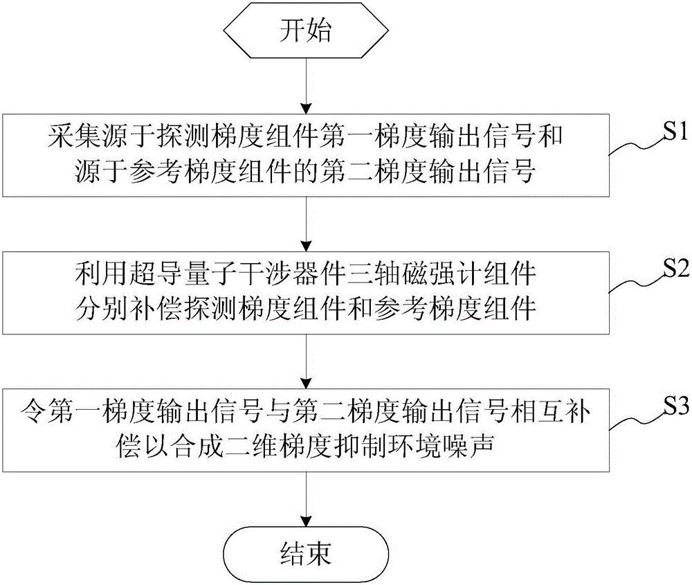
[0042] Compared with the traditional method, the environmental noise suppression method provided in this embodiment does not need to separately increase a step reference value of the environmental magnetic field, and uses a gradiometer that is consistent with the detection channel preparation process and detection volume as a reference, and is placed in a horizontal position. In the direction, the correlation characteristics of the response of the gradiometer itself are used to compensate, so as to achieve efficient noise suppression performance.
[0043] This embodiment provides an environmental noise suppression method, which is applied to environmental noise suppression equipment. The environmental noise suppression equipment includes a detection gradient component, a reference gradient component, a superconducting quantum interference device three-axis magnetometer component, Read the circuit. In this embodiment, a SQUID (SuperconductingQuantum Interference Device) measurement environment needs to be set up before the implementation of the environmental noise suppression method. Under the SQUID measurement environment, a probe gradient component, a reference gradient component, and a superconducting quantum interference device three-axis magnetic field must be prepared. 计Component. In this embodiment, based on the same manufacturing process, the SQUID detection gradient component and the reference gradient component are prepared separately, and the detection components of the two remain the same. According to the actual preparation process, a traditional three-axis magnetometer can be prepared.
[0044] See figure 1 , Is shown as a schematic flowchart of an environmental noise suppression method in an embodiment. Such as figure 1 As shown, the environmental noise suppression method includes the following steps:
[0045] S1, a detection gradient channel is formed between the detection gradient component and the parameter reading circuit, and another reference gradient channel is formed between the reference gradient component and the parameter reading circuit. The first gradient output signal from the detection gradient component and the second gradient output signal from the reference gradient component are acquired through the detection gradient channel and the reference gradient channel. The first gradient output signal is the output voltage signal of the detection gradient channel. The second gradient output signal is the output voltage signal of the reference gradient channel.
[0046] S2, using the superconducting quantum interference device three-axis magnetometer component to compensate the detection gradient component and the reference gradient component respectively; as a reference component, the superconducting quantum interference device three-axis magnetometer component is used to assist the compensation detection The deviation of the response between the gradient component and the reference gradient component.
[0047] S3. The first gradient output signal and the second gradient output signal are mutually compensated to synthesize a two-dimensional gradient to suppress environmental noise. In this embodiment, the step of making the first gradient output signal and the second gradient output signal compensate each other is to instruct the second gradient output signal and the first gradient output signal to perform amplitude subtraction. See figure 2 , Shown as a schematic diagram of the experimental results of two-dimensional gradient synthesis. Such as figure 2 As shown, the horizontal axis represents time, and the vertical axis represents magnetic field amplitude. The top is the schematic diagram of the amplitude of the first gradient output signal, the middle is the schematic diagram of the second gradient output signal, and the bottom is the synthesis after two-dimensional gradient synthesis. Schematic diagram of signal amplitude.
[0048] The environmental noise suppression method described in this embodiment uses the correlation characteristics between coil processes to perform noise suppression without considering a complicated one-step reference, thereby simplifying the entire detection system while ensuring high-performance noise suppression.

Example Embodiment

[0049] Example two
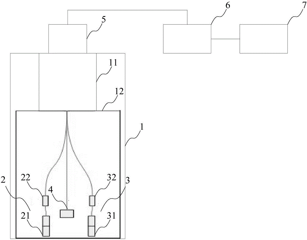
[0050] This embodiment provides an environmental noise suppression device 10, please refer to image 3 , Shown as a schematic diagram of the principle structure of an environmental noise suppression device in an embodiment. Such as image 3 As shown, the environmental noise suppression device 10 includes:
[0051] Non-magnetic Dewar 1 with a accommodating space. see image 3 The non-magnetic Dewar 1 includes a non-magnetic Dewar stopper 11 and a low-temperature connection seat 12, and the non-magnetic Dewar stopper 11 is used to seal the non-magnetic Dewar to form a closed space.
[0052] The detection gradient component 2 and the reference gradient component 3 placed in the inner space of the non-magnetic Dewar 1. In this embodiment, the detection gradient component 2 is composed of a detection gradient coil 21 and a detection superconducting quantum interference device 22. The reference gradient component 3 is composed of a reference gradient coil 31 and a reference superconducting quantum interference device 32. In this embodiment, the detection gradient component 2 and the reference gradient component 3 are respectively placed in parallel on both sides of the inside of the cube base 12.
[0053] In this embodiment, according to the inner space of the non-magnetic Dewar 1, the distance between the detection gradient component 2 and the reference gradient component 3 is adjusted so that the reference gradiometer is as far away from the signal source as possible. The distance between the detection gradient component and the reference gradient component is less than or equal to the diameter of the non-magnetic Dewar stopper, and greater than 20 mm.
[0054] The superconducting quantum interference device three-axis magnetometer assembly 4 placed between the detection gradient component 2 and the reference gradient component 3 and placed above the detection gradient component and the reference gradient component is used to compensate the detection gradient respectively The component 2 and the reference gradient component 3, that is, the superconducting quantum interference device three-axis magnetometer component 4, are used as reference components to assist in compensating for the previous response deviation of the detection gradient component 2 and the reference gradient component 3. In this embodiment, the superconducting quantum interference device three-axis magnetometer assembly 4 includes three superconducting quantum interference device planar magnetometers; the superconducting quantum interference device three-axis magnetometer assembly 4 is fixed at the The cube base 12 is in three orthogonal directions and is located in the center of the detection gradient component 2 and the reference gradient component 3.
[0055] The readout circuit 5 connected to the detection gradient component, the reference gradient component, and the superconducting quantum interference device three-axis magnetometer component and placed on the top of the non-magnetic Dewar is used to adjust the detection gradient component, the reference gradient component, The working parameters of the three-axis magnetometer assembly of the superconducting quantum interference device make it work normally and lock the output; the SQUID lead is connected to the readout circuit 5. Adjust the working parameters of SQUID one by one so that the SQUID detection component is in a normal working state and locked. In this embodiment, a detection gradient channel is formed between the detection gradient component 2 and the readout circuit 5, and another reference gradient channel is formed between the reference gradient component 3 and the readout circuit 5.
[0056] The acquisition component 6 connected to the readout circuit 5 is used to acquire a first gradient output signal derived from the detection gradient component and a second gradient output signal derived from the reference gradient component. The first gradient output signal is the output voltage signal of the detection gradient channel. The second gradient output signal is the output voltage signal of the reference gradient channel.
[0057] The gradient synthesis component 7 connected to the acquisition component 6 is used to make the first gradient output signal and the second gradient output signal compensate each other to synthesize a two-dimensional gradient to suppress environmental noise. The gradient synthesis component in this embodiment is specifically configured to perform amplitude subtraction between the second gradient output signal and the first gradient output signal.

PUM

no PUM

Description & Claims & Application Information

We can also present the details of the Description, Claims and Application information to help users get a comprehensive understanding of the technical details of the patent, such as background art, summary of invention, brief description of drawings, description of embodiments, and other original content. On the other hand, users can also determine the specific scope of protection of the technology through the list of claims; as well as understand the changes in the life cycle of the technology with the presentation of the patent timeline. Login to view more.
Why Eureka
Try Eureka