Display control method, device and system

一种显示控制方法、显示控制的技术,应用在数字输出到显示设备、静态指示器、阴极射线管指示器等方向,能够解决不利量产、FPGA成本昂贵等问题

Active Publication Date: 2016-08-17
BOE TECH GRP CO LTD
View PDF7 Cites 19 Cited by
  • Summary
  • Abstract
  • Description
  • Claims
  • Application Information

AI Technical Summary

Problems solved by technology

However, the cost of FPGA corresponding to this kind of processing is very expensive, which is very unfavorable for mass production

Method used


Image

  • Display control method, device and system
  • Display control method, device and system
  • Display control method, device and system

Examples


Embodiment 1

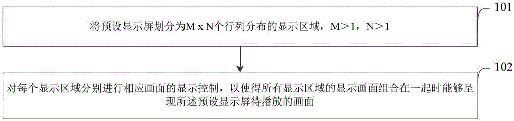
[0079] figure 1 A flow chart of the display control method provided by Embodiment 1 of the present invention is shown. see figure 1 , the display control method provided in this embodiment includes the following steps:

[0080] Step 101: Divide the preset display screen into M×N display areas distributed in rows and columns, where M>1 and N>1.

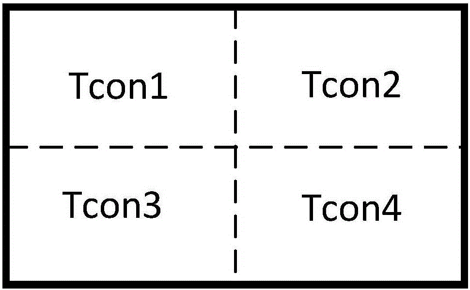
[0081] In this step, take the 8K4K display system as an example, according to figure 2The Tcon region division method of the screen driver board shown can divide the resolution of 7680×4320 into four 4K2K (3840×2160) display regions. The reason why the display screen is divided in this step is that after division, individual display control can be performed on each display area. For example, a manner in which one processing unit is in charge of one display area can be used for separate control. Such as figure 2 As shown, assuming that each board has a processing capability of 4K2K, then 4 boards can be combined on an 8K4K scree...

Embodiment 2

[0085] In this embodiment, it is assumed that there is a high-definition display screen with a large display area, and the high-definition display screen is now divided into M×N display areas distributed in rows and columns.

[0086] In order to solve the problem mentioned in the above embodiment that each display area is individually controlled to display a corresponding picture, in this embodiment, a processing unit is configured for each display area, where the processing unit can use a corresponding processing chip, such as System chip SOC (System OnChip) implementation.

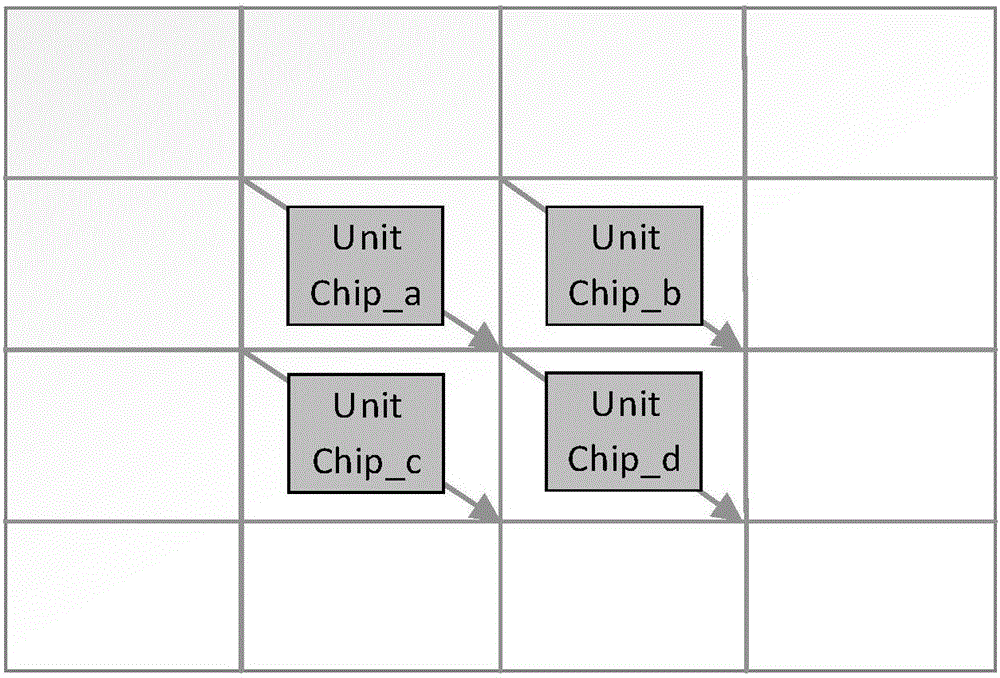
[0087] E.g image 3 The shown display screen is divided into 16 display areas arranged in rows and columns. Chips corresponding to the 4 display areas are placed for illustration. In fact, all display areas have corresponding chips corresponding to them.

[0088] In the description below, follow the data scanning direction from upper left to lower right. Certainly, the scanning direction of the displa...

Embodiment 3

[0132] The third embodiment provides a specific implementation manner of controlling each processing unit to sequentially acquire the current result display data part of the corresponding display area in the above step c.

[0133] In this embodiment, in the above step c, each processing unit is controlled according to the currently acquired main display data in the corresponding display area and the currently received For the edge interaction data sent from the processing unit in the group, use the preset filter processing algorithm and preset image processing algorithm stored in the processing unit to obtain the current result display data of the corresponding display area, specifically including:

[0134] Control each processing unit according to the currently received edge interaction data sent by the slave processing unit in the display group when the processing unit is the master processing unit in the display group, and the currently acquired edge interaction data in the ...


PUM


Abstract

The invention provides a display control method, device and system. The display control method includes following steps: dividing a preset display screen into display areas in MxN row-column distribution, wherein each of M and N is greater than 1; performing display control on a corresponding picture of each display area to enable presenting of a picture to be played by the preset display screen when the display pictures of all display areas are combined. By using the display control method and device, signal processing of an ultrahigh-resolution display screen can be realized in a mode of combining multiple low-cost chips, so that cost is lowered and mass production is facilitated.

Description

technical field [0001] The present invention relates to the field of display technology, in particular to a display control method, device and system. Background technique [0002] With the development of ultra-high-definition display systems, the resolution of liquid crystal panels has become higher and higher, and the demand for signal processing capabilities of the system is also increasing. [0003] At present, the latest ultra-high-definition display screen does not have a corresponding ASIC chip, and only FPGA can handle the processing requirements of large amounts of data. However, the cost of FPGA corresponding to this kind of processing is very expensive, which is very unfavorable for mass production. Contents of the invention [0004] Aiming at the defects in the prior art, the present invention provides a display control method, device and system, so that the signal processing of the ultra-high-definition resolution display screen can be realized by combining m...

Claims


Application Information

Patent Timeline
Patent Type & Authority Applications(China)
IPC IPC(8): G06F3/14
CPCG06F3/14G09G3/3611G09G2300/026G06F3/1446G09G2360/06G09G2310/0232G09G3/2096G09G5/14G09G2310/08G09G5/391G09G3/20
Inventor 段然
Owner BOE TECH GRP CO LTD
Why Eureka
Try Eureka