
Image display control method and device in vr system and vr head-mounted device

An image display and image technology, applied in the field of virtual reality, can solve problems such as reducing system delay, insufficient image realism, high system delay, etc., to meet actual needs, improve picture realism and display effect, and enhance market competitiveness. Effect

Active Publication Date: 2020-09-11
GOERTEK INC
View PDF8 Cites 0 Cited by
  • Summary
  • Abstract
  • Description
  • Claims
  • Application Information

AI Technical Summary

Problems solved by technology

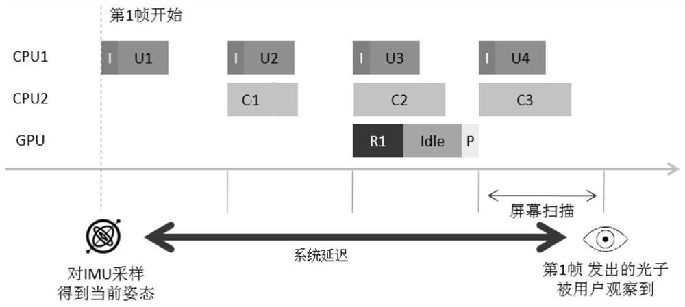
The pipelined design improves the utilization rate of each component and ensures high throughput. At the same time, it also brings high system delay. See figure 1 , from sampling the IMU to get the current pose to the photons emitted by the first frame displayed on the screen being observed by the user, a typical throughput-oriented rendering process brings a system delay (Motion to Photonlatency) of at least four screen refreshes cycle, and on a screen with a refresh rate of 90Hz, it will take 44.4 milliseconds, far exceeding the limit of 18 milliseconds that the human body can tolerate physiologically
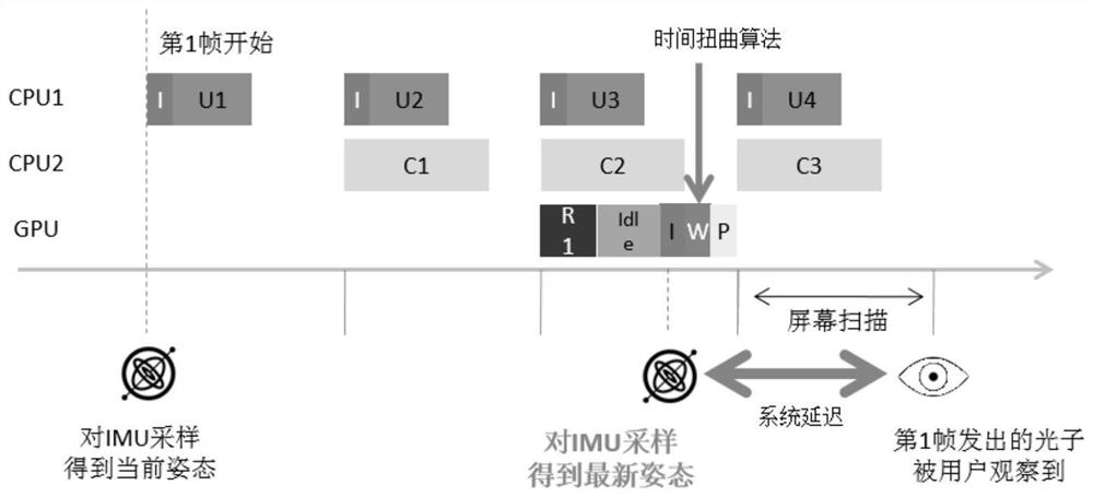
[0004] For this problem, there is a Time Warp Timewarp algorithm, which is used to distort (for example, shift, rotate, adjust or reproject) image frames to correct head motion or translation that occurs after the frame is rendered, thereby reducing system latency, However, for the sake of simplicity, the current Timewarp algorithm only processes images with 3 degrees of freedom (3DOF) poses, and the images processed by the Timewarp algorithm are not realistic enough to meet actual needs.

Method used


Image

  • Image display control method and device in vr system and vr head-mounted device
  • Image display control method and device in vr system and vr head-mounted device
  • Image display control method and device in vr system and vr head-mounted device

Examples


Embodiment Construction

[0054] In order to make the above objects, features and advantages of the present invention more comprehensible, the present invention will be further described in detail below in conjunction with the accompanying drawings and specific embodiments. Apparently, the described embodiments are some, but not all, embodiments of the present invention. Based on the embodiments of the present invention, all other embodiments obtained by persons of ordinary skill in the art without making creative efforts belong to the protection scope of the present invention.

[0055] The design idea of ​​the present invention is to improve the existing Timewrap algorithm and expand the application range of the Timewrap algorithm, so that it can be applied to scenes with 6 degrees of freedom pose changes and meet actual needs.

[0056] In order to facilitate a better understanding of the technical solutions of the embodiments of the present invention, the Timewrap algorithm and the prior art in which...


PUM


Abstract

The invention discloses a control method and device for image display in a VR system, and a VR head-mounted device. The method includes: monitoring the synchronization signal of the image frame in the VR system and obtaining the original 2D image; and setting a preset time before the arrival of the next synchronization signal point, the sensor data is sampled to obtain the latest pose information of the tracked object, the original 2D image is converted into the corresponding 3D image, and the corresponding pixel points of the 3D image are calculated according to the latest pose information and the pose information corresponding to the 3D image Based on the motion vector, the position of the pixels of the original 2D image is transformed, and the pixels of the vacant area appearing after the position transformation are filled to obtain the target frame; when the next synchronization signal arrives, the display of the target frame is triggered. The embodiment of the present invention expands the applicable scene of the Timewarp algorithm, enhances the realism of the image, and improves the image display effect.

Description

technical field [0001] The present invention relates to the technical field of virtual reality, in particular to a control method and device for image display in a VR system, and a VR head-mounted device. Background technique [0002] The VR headset (Head Mounted Display, HMD for short) continuously tracks the user's head posture in real time through the posture sensor, and then uses the posture information to render two 2D images from the virtual 3D world, one for the left eye and one for the right eye. After the user's retina receives the image content, the built-in mechanism of the brain will analyze the three-dimensional effect, thereby realizing the VR (Virtual Reality, virtual reality) effect. Throughout the process, a core indicator is system latency, which refers to the length of time from obtaining the user's head pose to when the rendered image is completely displayed on the screen. Excessive system delay will cause the user's physiological senses to be inconsiste...

Claims


Application Information

Patent Timeline
Patent Type & Authority Patents(China)
IPC IPC(8): G06F3/01G06T15/00G06T19/00
CPCG06F3/01G06T3/4007G06T7/246G06T2207/10016G06T2207/20021H04N13/271H04N13/344G02B27/0093G02B27/0101G02B2027/0138G02B2027/014G06T15/00G06T2207/20G06F3/011G06T17/00H04N13/261G06T3/18
Inventor 蔡磊戴天荣
Owner GOERTEK INC
Learn More