
Automatic laminating device for viscous solar battery welding strip

A solar cell and bonding device technology, applied in the direction of circuits, photovoltaic power generation, electrical components, etc., can solve the problems of large power consumption of motors, high cost, and inability to accurately repeat pasting, so as to save electricity and device costs, Avoid any shaking effect

Inactive Publication Date: 2016-08-17
周靖
View PDF3 Cites 2 Cited by
  • Summary
  • Abstract
  • Description
  • Claims
  • Application Information

AI Technical Summary

Problems solved by technology

[0004] However, the existing adhesive solar cell ribbon automatic bonding device still has the following disadvantages. First, when the cutter cuts the adhesive solar cell ribbon, the end of the adhesive solar cell ribbon will shake arbitrarily, causing the sticky solar cell The end of the ribbon is pasted to other internal parts of the adhesive solar cell ribbon automatic bonding device, so that the next time it is used, the end of the adhesive solar cell solder ribbon must be removed from the internal parts of the adhesive solar cell solder ribbon automatic bonding device Only when the adhesive solar cell ribbon is torn off can the operation of pasting the adhesive solar cell ribbon be carried out smoothly; the second point, since the adhesive solar cell ribbon is simply attached to the solar cell by using the pressure roller, the gap between the adhesive solar cell ribbon and the solar cell It is easy to entrain air bubbles, so that the adhesive solar cell ribbon and the solar cell cannot be completely bonded; the third point is that the adhesive solar cell ribbon is not well positioned on the solar cell, so it cannot be accurately pasted on the same position repeatedly ; The fourth point, because both the pressure wheel and the cutter must be driven by the motor, but the power consumption of the motor is large and the cost is high, so the production and installation costs are relatively high, and it is urgent to improve

Method used


Image

  • Automatic laminating device for viscous solar battery welding strip
  • Automatic laminating device for viscous solar battery welding strip
  • Automatic laminating device for viscous solar battery welding strip

Examples


Embodiment Construction

[0027] The following will clearly and completely describe the technical solutions in the embodiments of the present invention with reference to the accompanying drawings in the embodiments of the present invention. Obviously, the described embodiments are only some, not all, embodiments of the present invention. Based on the embodiments of the present invention, all other embodiments obtained by persons of ordinary skill in the art without creative efforts fall within the protection scope of the present invention.

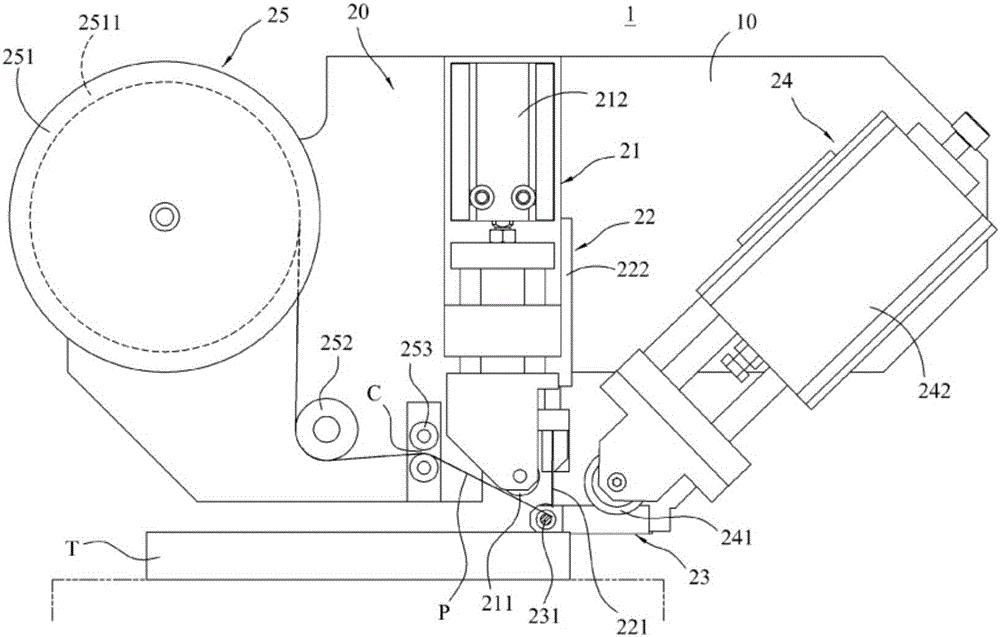
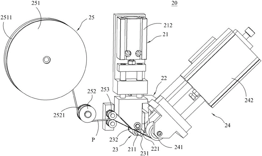
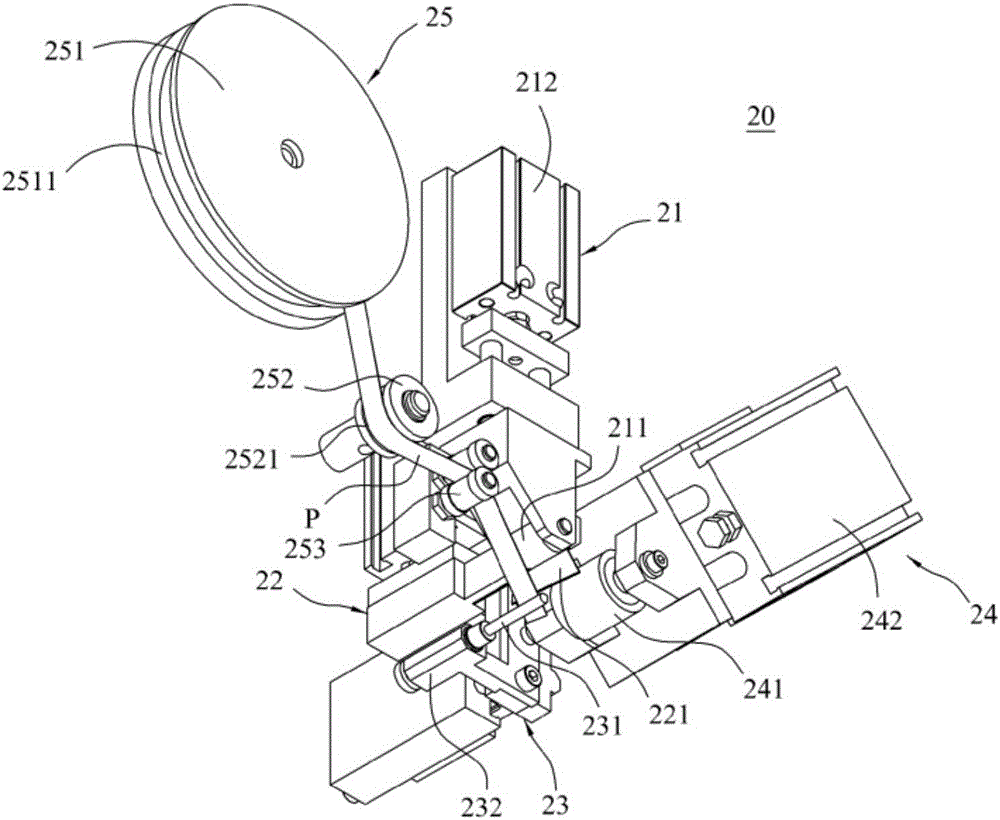
[0028] Please refer to Figure 1 to Figure 3 As shown, they are a combination schematic diagram of the present invention, a three-dimensional combination schematic diagram of an adhesive solar cell ribbon sticking mechanism, and another three-dimensional combination schematic diagram of an adhesive solar battery ribbon sticking mechanism. The present invention provides an automatic bonding of an adhesive solar battery ribbon The device 1 is used for bonding the adh...


PUM


Abstract

The invention discloses an automatic laminating device for a viscous solar battery welding strip. The automatic laminating device comprises a rack and a viscous solar battery welding strip pasting mechanism, wherein the mechanism is arranged on the rack and comprises a pressing assembly, a cutting assembly and a positioning assembly; the pressing assembly comprises a pinch roller and a first driver; the first driver is connected with the pinch roller; the first driver is used for driving the pinch roller to be pressed against the viscous solar battery welding strip and to be attached to a solar battery; the cutting assembly is arranged at one side of the pressing assembly; the cutting assembly comprises a cutter and a second driver; the second driver is connected with the cutter; the second driver is used for driving the cutter to cut off the viscous solar battery welding strip; the positioning assembly is arranged at the lower part of the cutting assembly and comprises a telescopic rod and a third driver; the third driver is connected with the telescopic rod; and the third driver is used for driving the telescopic rod to extend outside to paste the end part of the viscous solar battery welding strip.

Description

technical field [0001] The invention relates to a device for attaching adhesive solar battery ribbons, in particular to a device for automatically attaching adhesive solar battery ribbons to solar cells. Background technique [0002] The industry often uses adhesive solar cell ribbon to seal the product after it is produced and packed, so as to protect the product during product delivery or achieve the effect of convenient handling. Therefore, in order to make the sealing speed faster and more convenient, it developed The sticky solar cell ribbon automatic bonding device is used to replace the manual sticky solar cell soldering tape sealing operation; however, the sticky solar cell soldering tape automatic bonding device can be used not only for sealing, but also for other applications that require sticky solar cell In the case of ribbon, for example, the connection of circuit boards or the interconnection of other boards. [0003] The existing adhesive solar cell ribbon au...

Claims


Application Information

Patent Timeline
IPC IPC(8): H01L31/18
CPCH01L31/188Y02E10/50Y02P70/50
Inventor 周靖
Owner 周靖
Learn More