
Broadband compact type microstrip array antenna

A microstrip array, compact technology, applied in antennas, antenna arrays, antenna grounding devices, etc., can solve the problems of radiation pattern distortion, polarization impurity, and high cost of thick substrates

Active Publication Date: 2016-08-17
邵振海
View PDF2 Cites 16 Cited by
  • Summary
  • Abstract
  • Description
  • Claims
  • Application Information

AI Technical Summary

Problems solved by technology

However, these methods have certain shortcomings, such as the high cost of using a thick substrate, the use of a substrate with a low dielectric constant is large in size, which is not conducive to miniaturization, the design of a multi-layer structure is complicated, and the assembly cost is too high. The patch antenna leads to the distortion of the radiation pattern and the problem of polarization impurity

Method used


Image

  • Broadband compact type microstrip array antenna
  • Broadband compact type microstrip array antenna
  • Broadband compact type microstrip array antenna

Examples


Embodiment Construction

[0016] The specific embodiments of the present invention are described below so that those skilled in the art can understand the present invention, but it should be clear that the present invention is not limited to the scope of the specific embodiments. For those of ordinary skill in the art, as long as various changes Within the spirit and scope of the present invention defined and determined by the appended claims, these changes are obvious, and all inventions and creations using the concept of the present invention are included in the protection list.

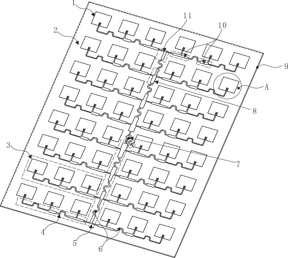
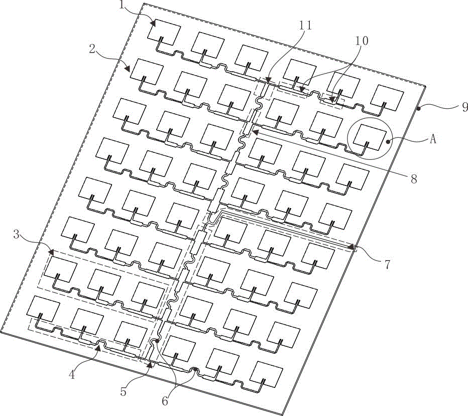
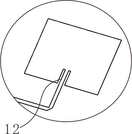
[0017] Such as figure 1 and figure 2 As shown, the broadband compact microstrip array antenna includes a dielectric substrate 2, a microstrip patch 1 disposed on the upper surface of the dielectric substrate 2, and a metal floor 9 disposed on the lower surface of the dielectric substrate 2; the dielectric substrate 2 is a dielectric The TLY-5 polymer dielectric substrate 2 with a constant of 2.2 has a thickness of 1.143mm...


PUM


Abstract

The invention discloses a broadband compact type microstrip array antenna. An even number of lines of microstrip patches and an even number of columns of microstrip patches are arranged on a dielectric substrate; two x-direction series-wound feedback networks which are connected together through a feedback structure are arranged on the dielectric substrate along an x-axis direction; the x-direction series-wound feedback networks divide the even number of columns of microstrip patches into two parts; the microstrip patches on the left part and the microstrip patches on the right part of each row are connected with adjacent y-direction series-wound feedback networks to form a sub array; the microstrip patches of the left side sub array in each row and the microstrip patches for forming the right side sub array in each row are connected with one y-direction series-wound feedback network separately to feed; the left side sub arrays in each row are connected with the right side sub arrays in each row in parallel; two sub arrays, which are adjacent along the x direction, of the 1 / 2 antenna array up and down are connected in series; and the array formed by the microstrip patches on the upper half part of the dielectric substrate and the array formed by the microstrip patches on the lower half part of the dielectric substrate are connected in parallel along the x-axis direction through the feed structure.

Description

technical field [0001] The invention relates to the technical field of microstrip array antennas, in particular to a broadband compact microstrip array antenna. Background technique [0002] With the rapid development of modern communication systems, the volume of communication equipment has been continuously reduced, and the communication frequency band has been continuously developed to wide-band and high-frequency bands. miniaturization and broadband development. [0003] Microstrip antennas are favored by people because of their small size, light weight, low profile, flexible feeding methods, low cost, and easy to conform to aircrafts. However, traditional microstrip antennas have narrow impedance bandwidths. The bandwidth of the antenna is only about 5%. The narrow-band characteristic of the traditional microstrip antenna has become the main obstacle to limit its wide application, so it is of great significance to widen the bandwidth of the microstrip antenna. In rec...

Claims


Application Information

Patent Timeline
Patent Type & Authority Applications(China)
IPC IPC(8): H01Q1/38H01Q1/48H01Q1/50H01Q21/06
CPCH01Q1/38H01Q1/48H01Q21/0006H01Q21/065
Inventor 邵振海李鹏凯宋鸿
Owner 邵振海
Learn More